Build a 3d-printable water turbine re-using the brushless motor / generator design. In contrast to the wind turbine this system should produce a considerable amount of energy - not just powering a few LEDs. Water is used from a little brook, or (for testing) just tap water. I.e. water with a little bit of pressure, and relative low flow rate.
For my tests at home (without having a brook), I wanted to know, how much energy I can get from the tap. I.e. the water exiting the nozzle of the garden hose can be used to drive a turbine. Having 30 PSI water pressure and the volume of a children’s pool with 1.5 m^3, the energy is a bit more than 100 Wh. Enough energy to charge a battery of a medium size RC-car.
iCertainly a Pelton wheel would do a good job, but before starting the design, I wanted to be sure, if other approaches were maybe even simpler. But even more important: will a 3d-printed structure withstand water pressure?
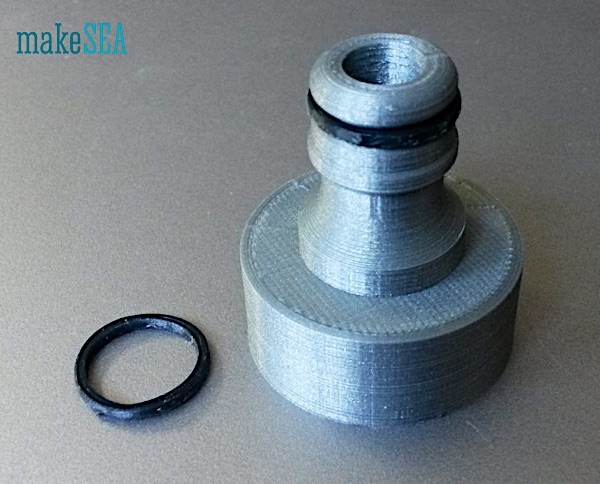
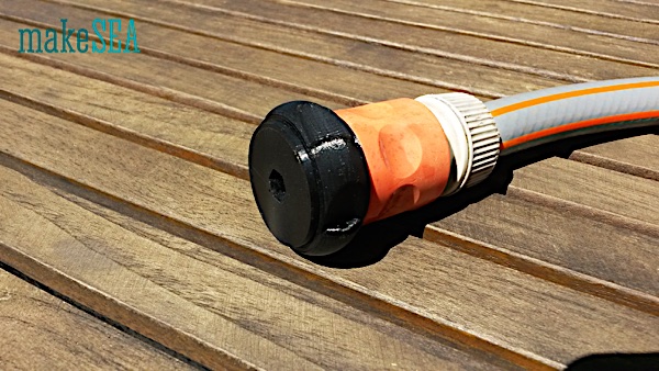
In order to test water and pressure, I initially designed an adapter for my garden hose (Gardena). The adapter actually didn’t have an outlet but it was a short, closed pipe. So it was possible to see, if it is water-tight. For 3d-printing I’ve increased the material-flow to 110%, and the outer pipe wall with 2.4 mm thickness had 6 perimeter shells (0.4 mm nozzle).
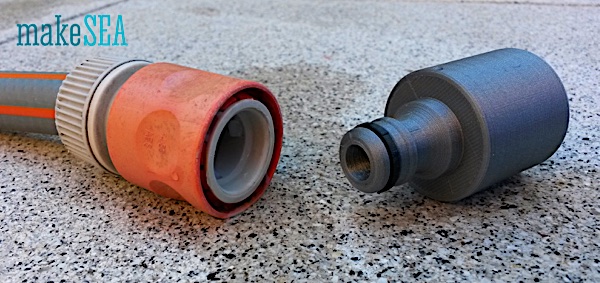

With full tap water pressure, there is a bit of water leaking through the 3d-printed layers, but the amount is very little (see also video). Certainly not useful for some water-installation in a bathroom, but good enough for the turbine. More important, the 3d-printed layers are strong and don’t crack or explode.
As an alternative to the pelton wheel, I wanted to know if some sort of sprinkler-wheel maybe also works. So I’ve extended the Garden-hose-adapter, and added a wheel with 5 tangential outlets.
The video shows this special turbine in action. The rotation speed is not very fast, a lot of water is leaking through the bearings, the torque is also very low. My design is far away from being useful as a turbine. It’s just good to get wet on a hot summer day - maybe fun for children ;-)
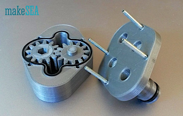
The next experiment is a reverse running gear-pump. The advantage of such a design is the efficient use of static water pressure and very little flow. Unfortunately in my design the gap between gear-teeth and house was too large - too much water is leaking through. A tighter gap didn’t work either, because wheels were blocking at certain angles. Probably such a design works only with well machined and accurately circular surfaces.
Conclusion: don’t try to 3d-print movable objects, which require a water-tight sealing. For this reason I skipped other designs like a Francis-turbine. Maybe a Kaplan-turbine would work, but now it’s time to try the Pelton Wheel.
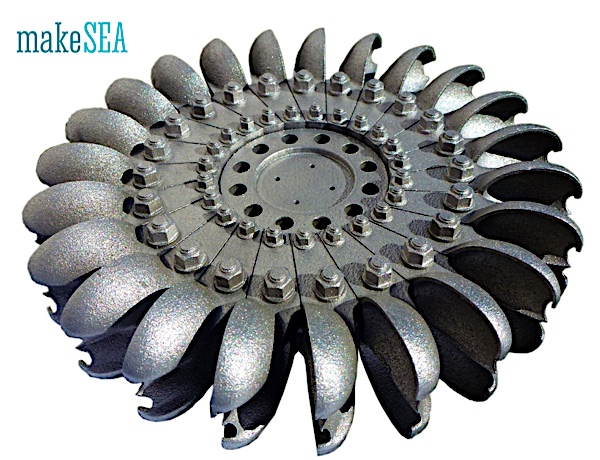
(image source: http://palmerdesign.co.nz/?attachment_id=487)
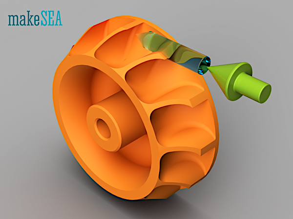
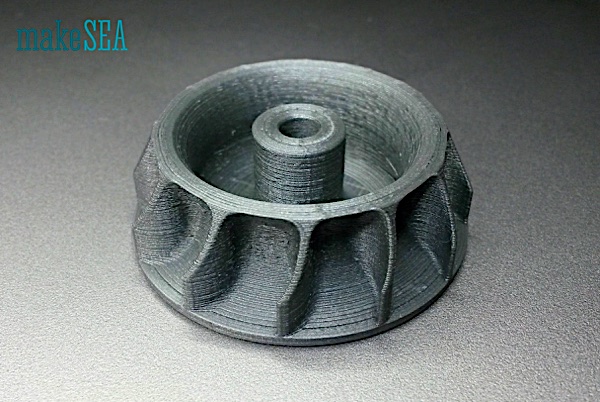
A classical Pelton wheel has shovels deflecting the water-jet symmetrical to both sides (see also https://en.wikipedia.org/wiki/Pelton_wheel). Such a design is well 3d-printable with an SLS-printer, but not with an FDM-printer. So I decided to split the wheel and build it asymmetrically. In case the axial forces would be a problem, a second, mirrored wheel could be attached to the same shaft.
In order to understand the functionality of the pelton wheel we can check the following three situations:
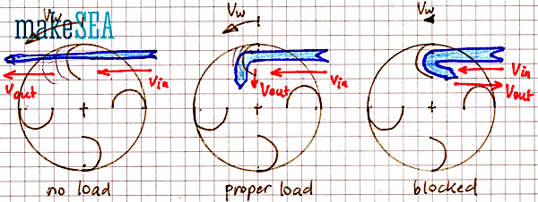
A. Without load the wheel spins freely with the same speed as the water-jet exiting from the nozzle: v_out = v_in, v_w = v_in. The kinetic energy of the water isn’t used - it get’s lost, when the water hits the wall.
B. With the proper load, the water-jet is stopped to zero speed: v_out = 0, v_w = v_in / 2. The wheel receives the full kinetic energy of the water jet. That’s the ideal working state.
C. If the wheel is blocked, the water-jet is basically reversed by the shovels. The kinetic energy of the water-jet remains unchanged, it just changes direction, and get’s lost when it hits the wall. v_out = -v_in, v_w = 0
Later this behavior will need to be used to optimize the efficiency of the wheel. In order to get the maximum power from the water-jet, the load needs to be adjusted, while the exiting water-jet is observed. The jet shall not go through the wheel, nor should it be reversed. Ideally the water drops with zero speed off the wheel.
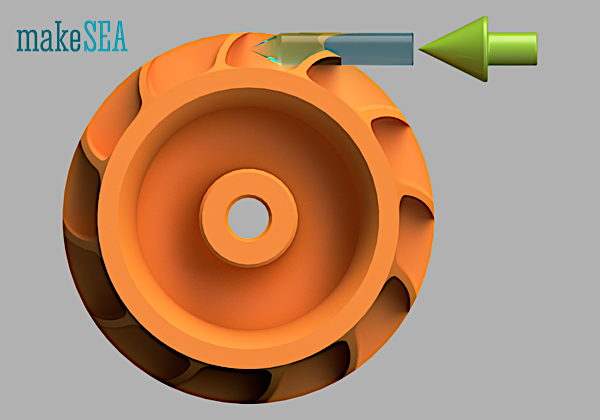
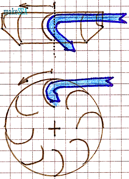
The wheel has a diameter of 45 mm. A water-jet with 4 mm diameter enters tangentially at one side of the wheel. It shall not enter in the center, because the water needs to have space in order to be properly deflected to the side.
For very simple testing, I’ve used the regular nozzle from the garden hose, and let the wheel spin freely. It spins with roughly 6’000 RPM. When blocking the wheel, the water is in-deed reversed (I got very wet). It wasn’t possible to experiment with the ideal load, but the torque was considerable high when blocking the wheel.
Water Turbine related videos: