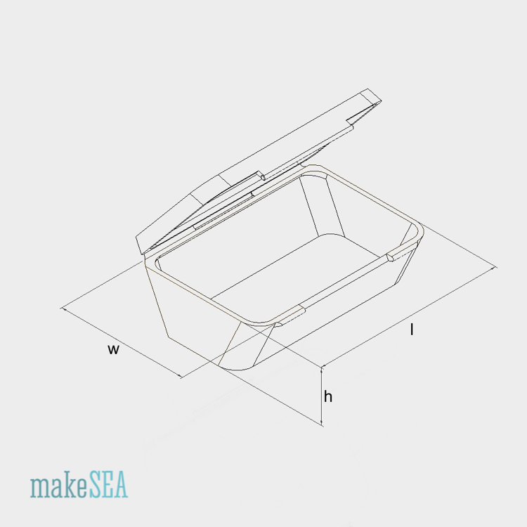
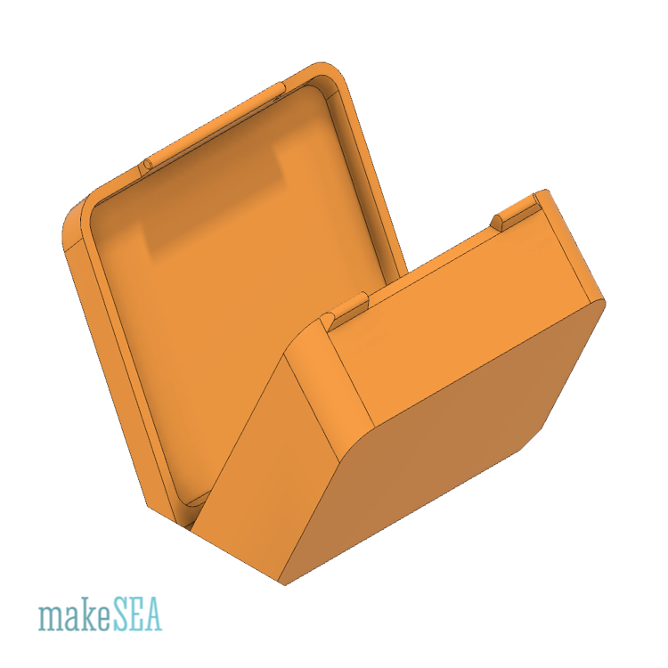
File Name: "Box Hex wXXX lXXX hXXX.stl"
w - width
l - length
h - height
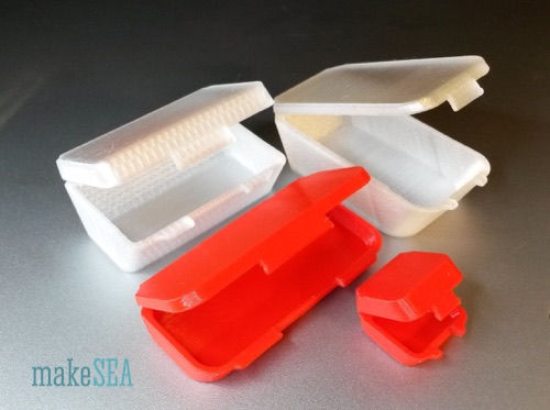
Box prints in one piece, has a folding hinge and a snap lock. For printing, the hinge needs to lay flat on the print bed. The hinge is 0.2mm thick - i.e. it’s recommended to use 0.1mm layer resolution in order to have 2 solid layers printed as a hinge. Various sizes tested in PETG on UM2 and R2x.
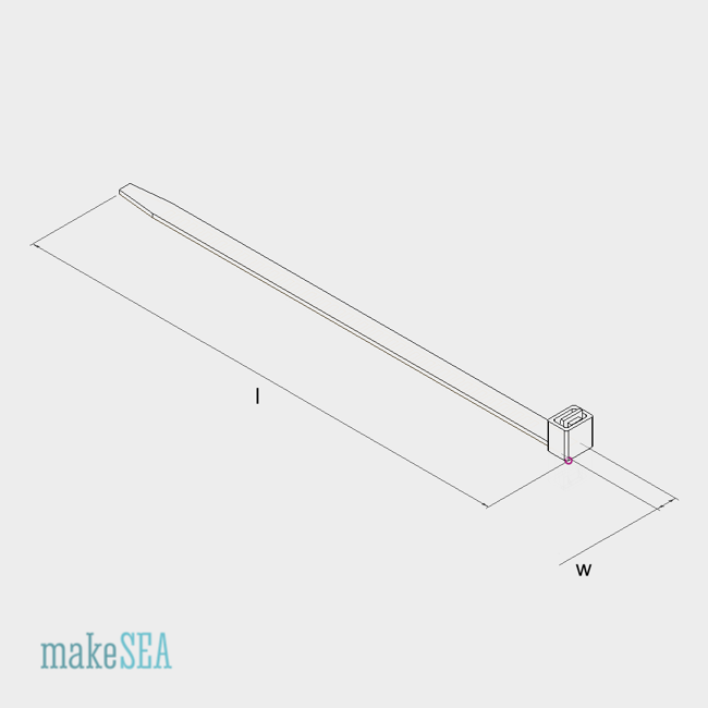
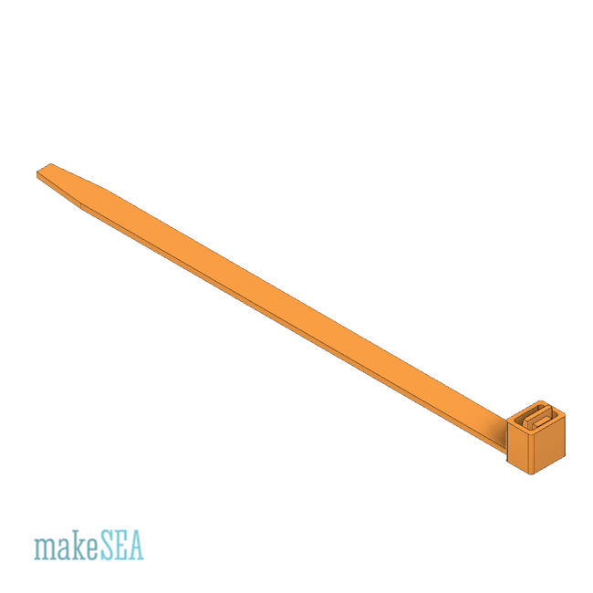
File Name Pattern: “Cable Tie wXXX lXXX.stl”
w - Width
l - Length
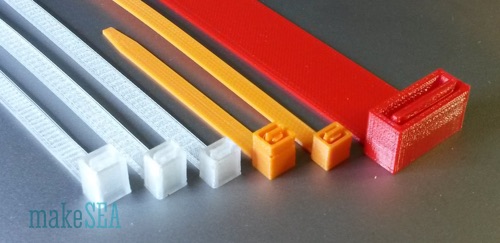
Recommended layer height for printing is 0.2mm. Tested with PETG on UM2 and R2x. Also tested PLA, which is very brittle and not recommended for a cable tie.
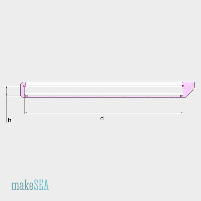
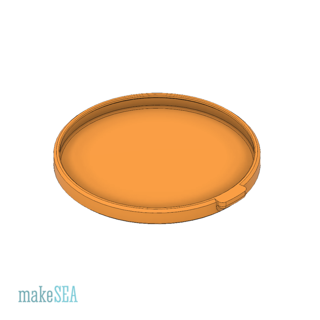
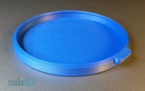
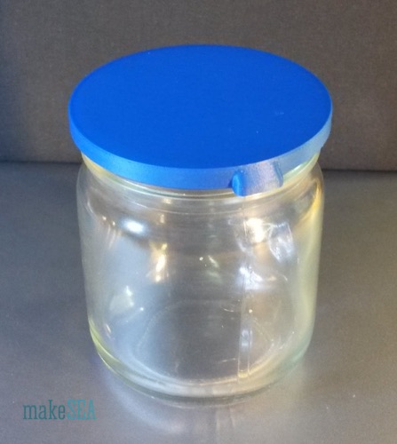
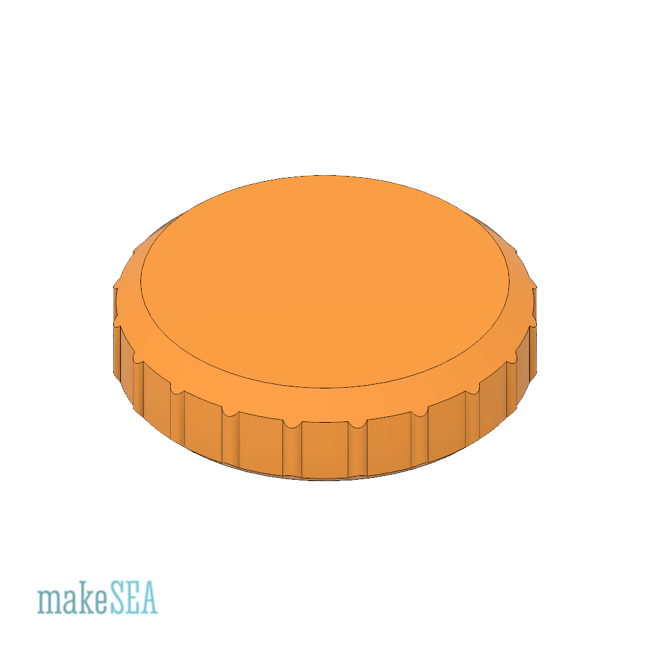
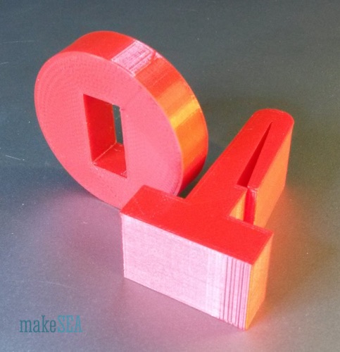
File Name Pattern: “Glass Jar Lid Snap hXX dXX.stl”
h - Height: from top rim to notch
d - Diameter of Glass Jar rim (not notch)
Tested with PETG and BDP. Even though PETG is said to be relatively bendable, it did break sometimes in my tests. Also a problem is finding the best matching diameter - if the material is not very stretchable, the range, where the lid is working is very narrow.
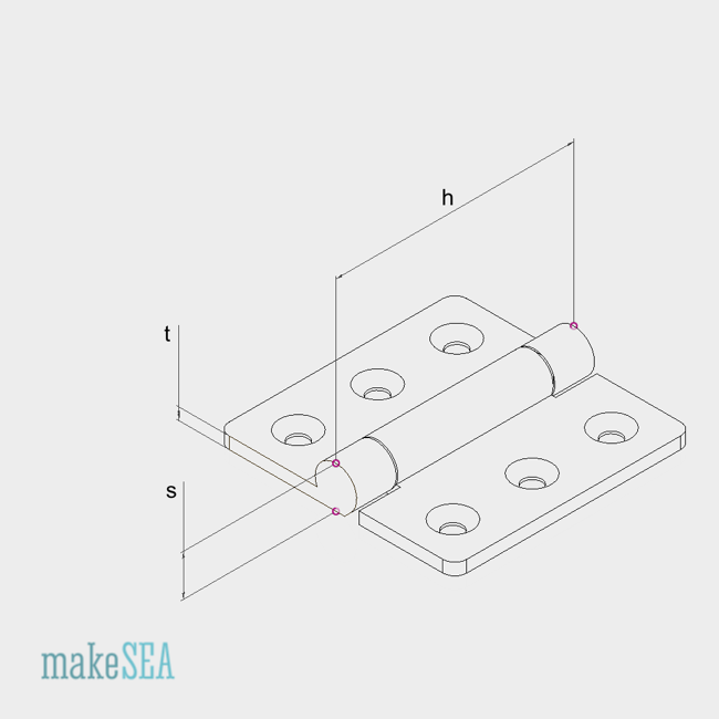
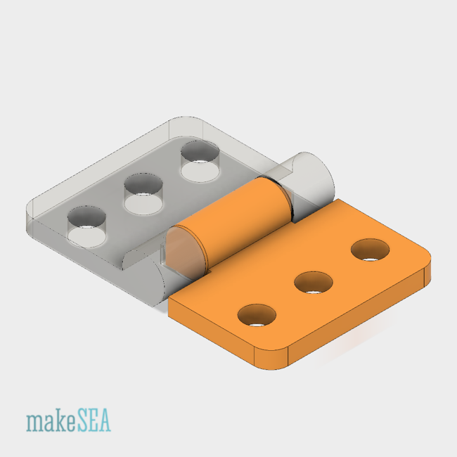
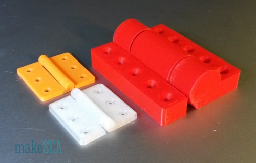
File Name Pattern: “Hinge Interlocking sXX tXX hXX.stl”
s - Size of rotating part (diameter)
t - Thickness; h - Height
The hinge prints in one piece. The two parts are interlocking (can’t take apart). The gap between the two parts are by default 0.2mm. This requires accurate print settings. My R2x failed - needed 0.4mm gap because of the play of the y-axis. UM2 worked well.
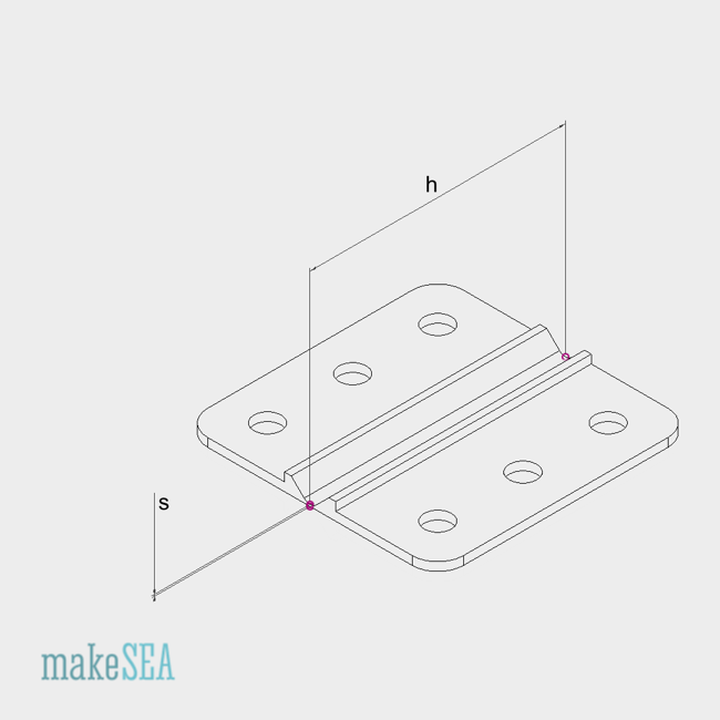
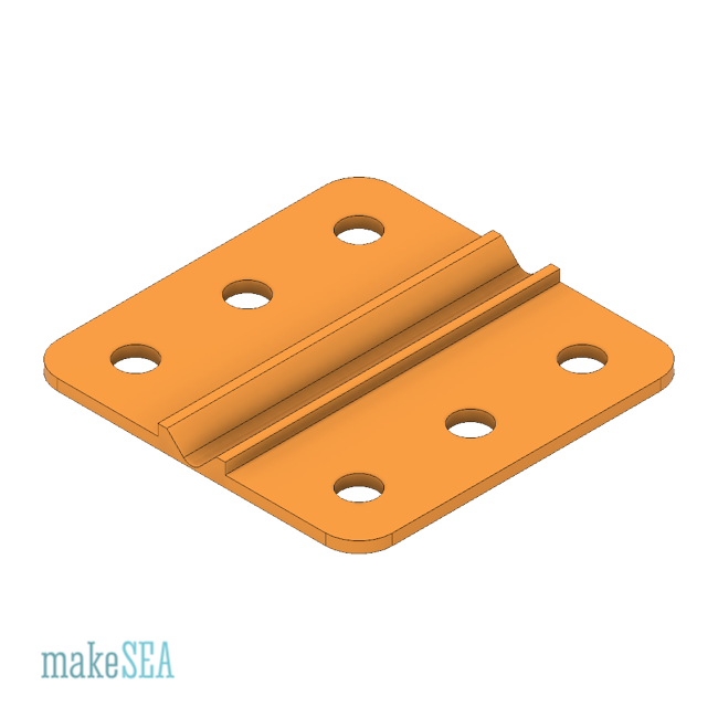
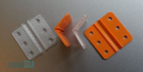
File Name Pattern: “Hinge Living Flexion sXX tXX hXX.stl”
s - Thickness (size) of bending part
t - Thickness of mount part (with screw holes)
h - Height
It’s recommended to use a flexible material (PETG, BDP, etc.). PLA probably breaks quickly. The bending part needs to be as thin as possible in order to last for a while - larger thickness will cause bigger stress and sooner fail. Bending thickness of stl-files is either 0.2mm or 0.3mm. For 3d-printing select slicing layer thickness of 0.1mm or 0.15mm so the hinge has 2 thin layers at the bending part. Because the material is plastically deformed, it will break sooner or later.
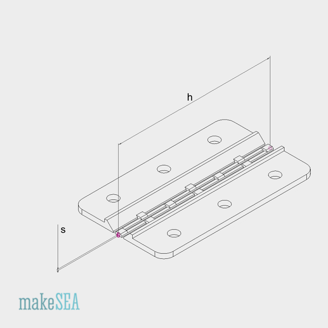
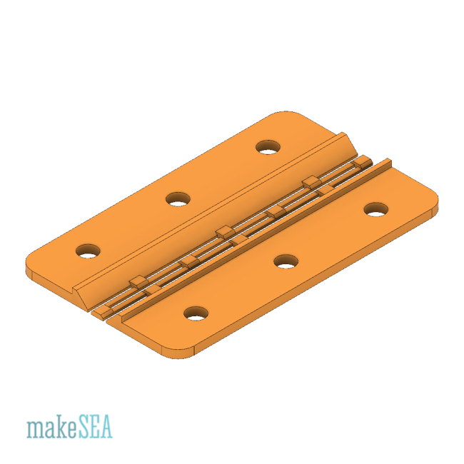
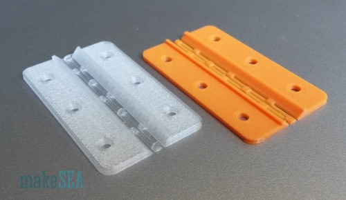
File Name Pattern: “Hinge Living Torsion sXX hXX.stl”
s - Thickness (size) of torsion parts
h - Height
In contrast to the flexing hinge, this hinge has thin parts, which are stressed only by torsion. The torsion bands are long enough to not do a plastic deformation. This should last much longer. However this hinge can not carry as much load as the flexing hinge. Even worked with PLA.
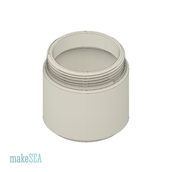
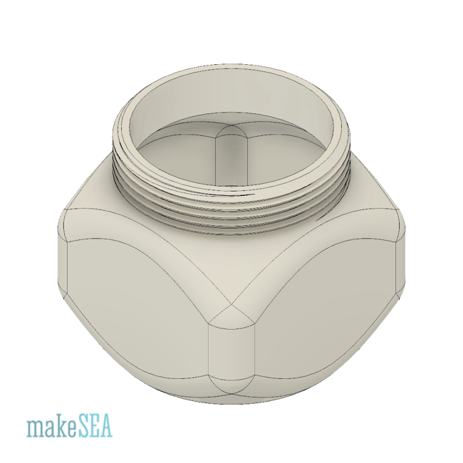
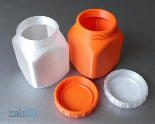
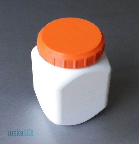
File Name Pattern:
d - Diameter
h - Height from very bottom to top rim
The Jar has a Lid with a 1.5mm thread. Overhang is 60° but it prints well with PETG on UM2. Not tested on R2x. Note: even if the Jar looks well airtight, it’s not. Even water can leak out. But it certainly can keep away dust.
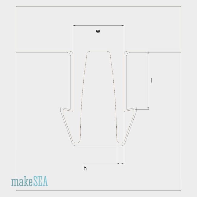
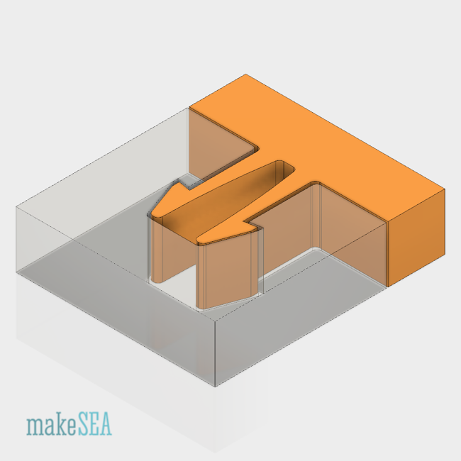
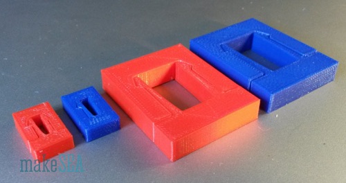
File Name Pattern: “Snap Fit Cantilever hXXX wXX lXX.stl”
h - Hook width
w - Width of hole
l - Length of hole
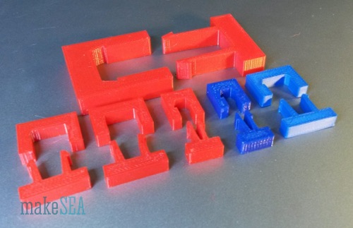
This Snap Fit is permanently locking - basically it can’t be dismounted. By designing a small hole at the location of the hook, the hook could be bent back by pushing a small pin through the hole (an option to make it unmountable). There is another design named “Snap Fit Cantilever B””, where the hook has a less sharp angle, which can be disassembled. The f3d-File has a parameter for the hook angle - the design is the same for both types of Snap Fit. While the shape of this Snap Fit is quite simple, the disadvantage is the relative long length for the hole: in order to make the beams enough flexible, the length should be at minimum 8 times larger than the hook width. It also depends on the material. For printing it’s recommended to use the layering as in the images above (due to the reduced robustness along z).


File Name Pattern: “Snap Fit Cantilever B hXXX wXX lXX.stl”
h - Hook width
w - Width of hole
l - Length of hole
It’s dismountable. Hook angle is 45° (if it was 90° it would be permanent). Tested with PETG. Not tested with PLA.
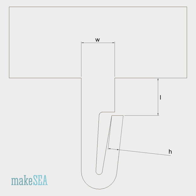
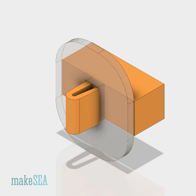
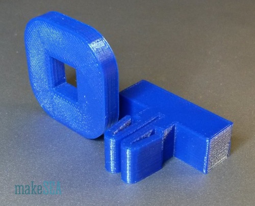
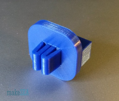
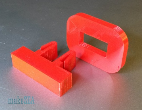
Name Pattern: “Snap Fit Clip hXXX wXX lXX.stl”
h - hook width
w - hole width
l - hole length
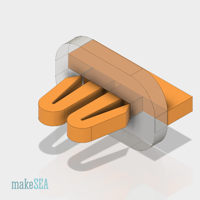
Advantage: very short hole length (beam). The flexible part of the beam/hook is on the other side of the hole. Similar as the cantilever snap fit, the size of this flexible par depends on the material, and the ratio of the overall beam length compared with the hook width should also be higher than 8. Basically this snap fit is not dismountable, but due to the sticking out flexible hook, it can be easily bent back ba hand. The f3d-file has a parameter for the hook angle, by changing it to 135° it can be transformed into “snap fit clip B”. Designs are tested with PETG.

(Sketch with dimensions shows hook angle for the permanent clip - it’s an adjustable as parameter in f3d-file)
Name Pattern: “Snap Fit Clip B hXXX wXX lXX.stl”
h - hook width
w - hole width
l - hole length
The design is not much different than the basic “Snap Fit Clip”. The slanted angle of the hook allows that the clip can be dismounted by just pulling it back. The angle is a parameter in the f3d-file. Recommended values are from 135° to 160° (depending on the required holding force and the selected material). Designs are tested with PETG.
Name Pattern: “Snap Fit Clip Double hXXX wXX lXX.stl”
h - hook width
w - hole width
l - hole length
This Double Snap Fit is basically the same as two mirrored basic clips. It has the same advantages, but in addition the two symmetrical hooks hold the mountable part more evenly. With only one hook it could dangle a bit (depending on the touching face on the other side). If the hole width is extremely large, it’s recommended to design two smaller holes (resp. use two mirror-inverted basic clips).

Name Pattern: “Snap Fit Clip Double B hXXX wXX lXX.stl”
h - hook width
w - hole width
l - hole length
See description of basic “Snap Fit Clip Double”. Difference is only the hoock angle in order to make it dismountable. The slanted angle of the hook allows that the clip can be dismounted by just pulling it back. The angle is a parameter in the f3d-file. Recommended values are from 135° to 160° (depending on the required holding force and the selected material). Designs are tested with PETG.
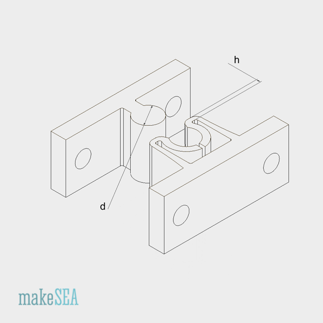
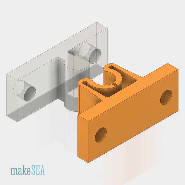
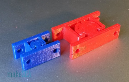
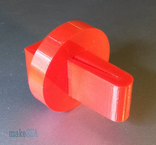
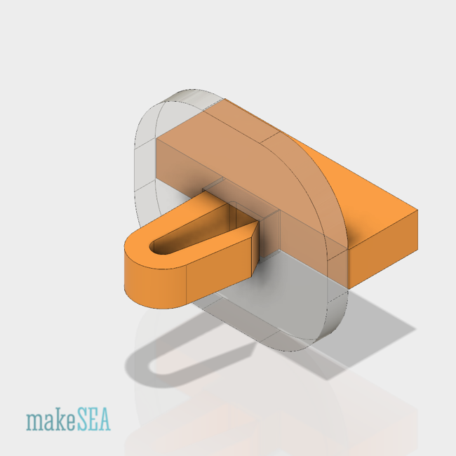
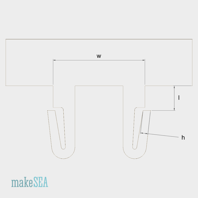
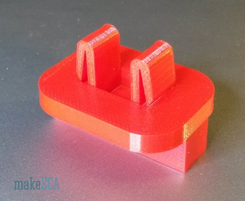
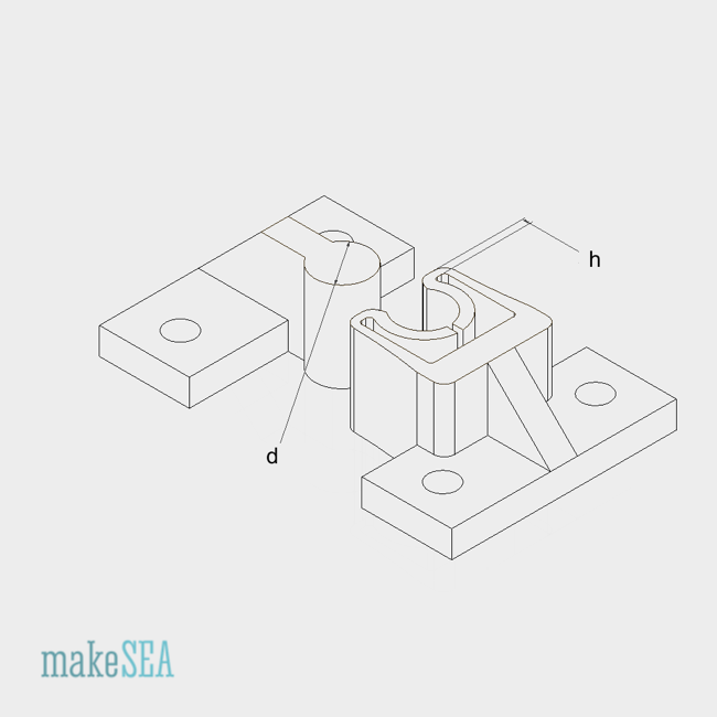
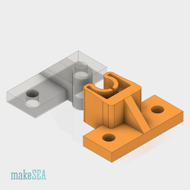
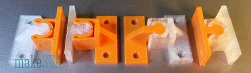
Name Pattern: “Snap Fit Round A hXXX dXX.stl”
h - hook width
d - knob diameter
It’s a dismountable snap fit. The holding force is relatively low (depending on the hook width). This makes it useful for a door lock. The design is related with the “Snap Fit Double B” with flipped hooks pointing towards each other. The knob is quasi the protruding middle part between two holes. If the two parts are snapped together, they can be twisted a bit like a hinge. By designing a smaller neck for the knob (or extending the cylindrical shape without neck), its rotation angle can be increased. The f3d-file has some more parameters. Tested with PETG and PLA.
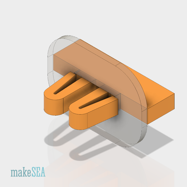
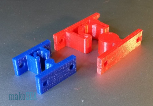
Name Pattern: “Snap Fit Round B hXXX dXX.stl”
h - hook width
d - knob diameter
It is basically the same design as “Snap Fit Round A”. Difference is the orientation of the mounting plate.
Name Pattern: “Spatula A tXX lXX wXXX.stl”
t - blade thickness
w - blade width
l - blade length
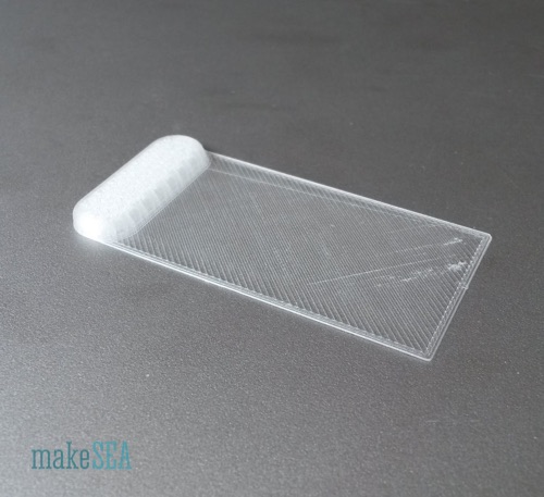
A spatula with a very basic rectangular shape. The blade front is slanted with 45°. The handle is a small extension on one edge of the blade, making the spatula more “handy”, and in particular makes the blade rigid along one dimension. Thickness can be very thin in order to make the spatula more flexible. It’s recommended to adjust the slicing diameter according the the blade thickness - it should print at minimum 4 layers. An even number of layers is also preferable, because the blade flexibility and robustness is more even. Flexibility also depends on the selected material. Tested with PETG and PLA.
Name Pattern: “Spatula A tXX lXX wXXX sXX.stl”
t - blade thickness
w - blade width
l - blade length
s - tooth distance
It’s the same design as “Spatula A“ but the blade is toothed. Useful for distributing even amounts of all kind of gles on a surface. In the model the tooth size depends on the tooth distance.
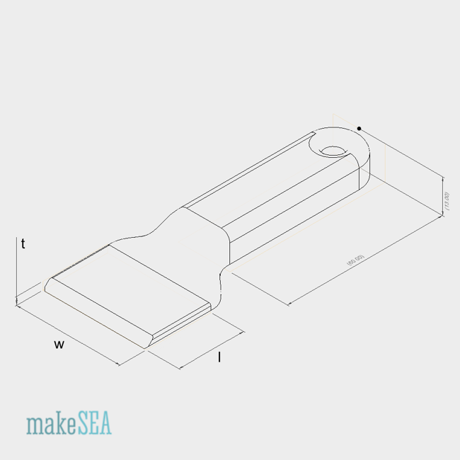

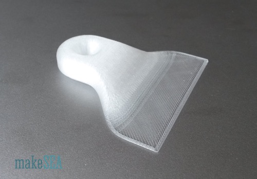
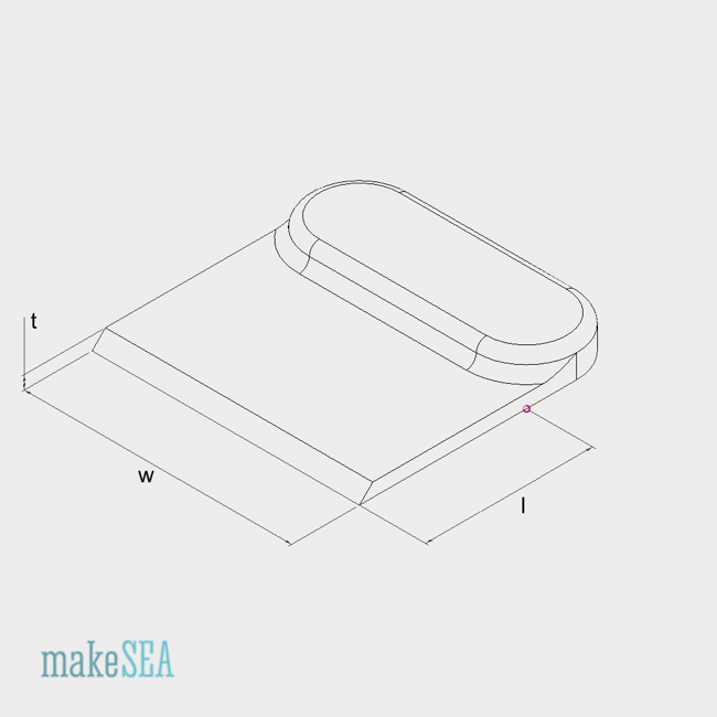
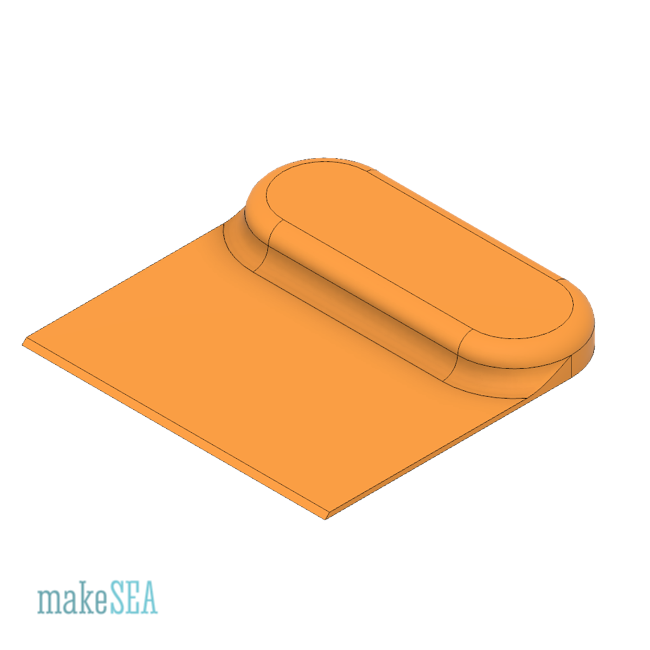
Name Pattern: “Spatula B tXX lXX wXXX.stl”
t - blade thickness
w - blade width
l - blade length
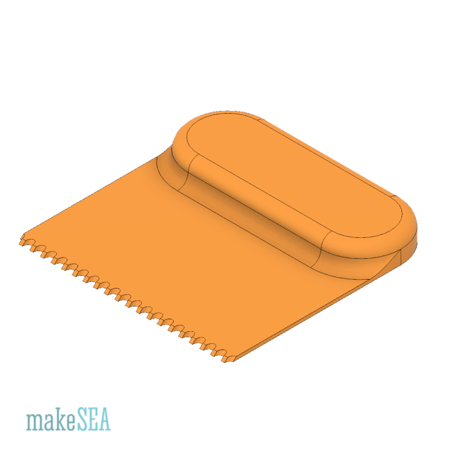
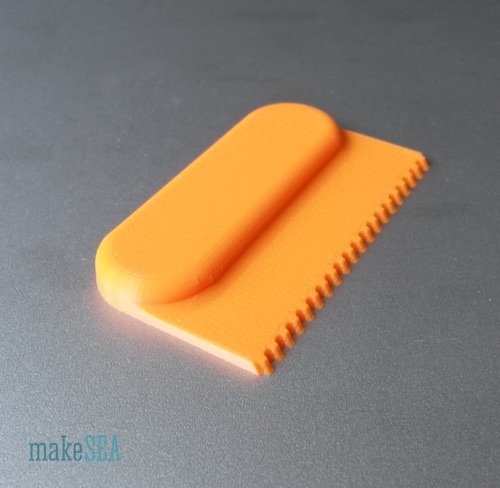
Same blade as “Spatula A” but a differently shaped handle. The handle in the STL files has a fixed size (60mm long, 12mm thick, 20mm width). Handle parameters and slant of blade front can be adjusted by a parameter in the f3d-file.
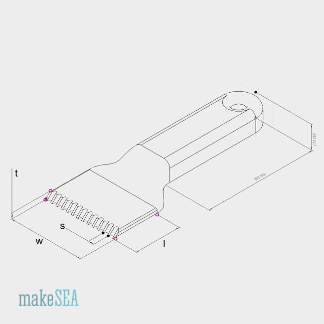
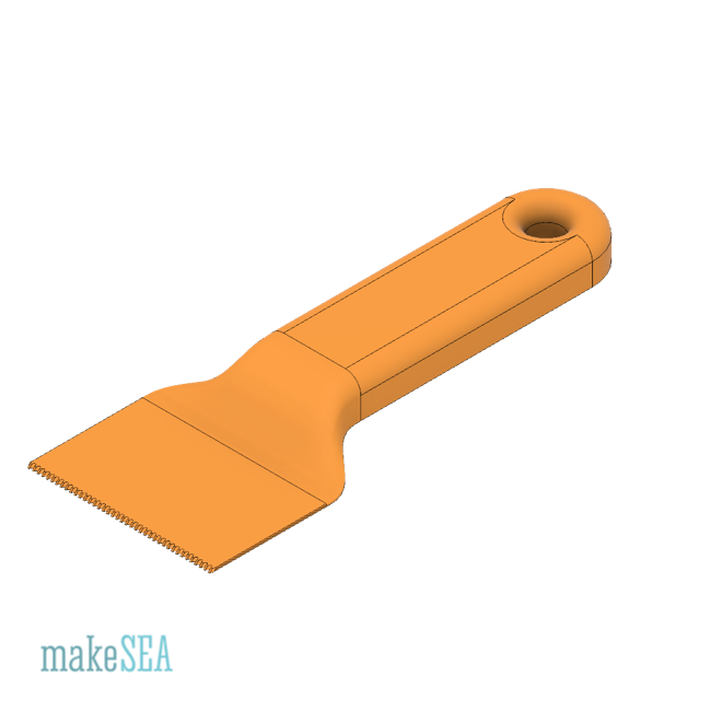
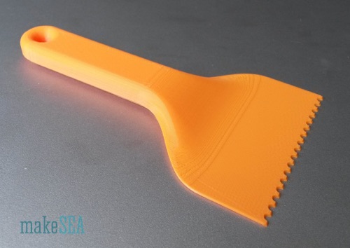
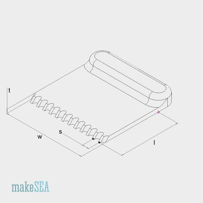
Name Pattern: “Spatula B tXX lXX wXXX sXX.stl”
t - blade thickness
w - blade width
l - blade length
s - tooth distance
It’s the same design as “Spatula B“ but the blade is toothed. Useful for distributing even amounts of all kind of gles on a surface. In the model the tooth size depends on the tooth distance.