(see also, Brushless Motor v.2)
In the beginning was the word - Chris asked me to buy conductive and magnetic PLA from Proto Pasta, and I should create something useful with it. The initial experience with this materials was sobering, instead of experimenting with special material properties, I had to fight to get it through the printer nozzle (see other blogs).
The conclusion for the conductive PLA is, that it can’t be used for high power applications, only for low power like a small efficient LED. The properties of conductive PLA and its application could easily be measured by using a simple Ohmmeter. Knowing the simple formulas U = R * I or P = R * I^2 it’s very easy to predict its behavior and its application as a conductor. It is useful like a customizable resistor with a resistance larger than 1kOhm.
It’s more sophisticated to explore possible applications of the magnetic PLA. Yes, a magnet can stick to it, so it would be possible to design a door lock using a regular permanent magnet, and some magnetic PLA. The magnetic (resp. ferromagnetic) properties could also be measured, but I didn’t have a suitable instrument. Anyway if I would know such material constants, I wouldn’t be able to evaluate an application with a simple formula. Compared with regular iron, the force of magnetic PLA attracted by a permanent magnet is only moderate. Nevertheless my focus was attracted to use the material as a core for some kind of coil (no surprise - I’m an Electrical Engineer by education).
Even though the magnetic PLA was maybe useless, it started a fire: I wanted to 3d-print a brushless motor, and I wanted to create a thing, which has some extra shaft-power, not just a rotating design study.
How to realize this? Either you start with complex theories and heavy formulas, or you just create something and later carefully analyze the reasons, why it doesn't work. 3d-printing is great for trial-and-error, and (by accident) I had some spare copper wire, permanent magnets, and ball bearings: ready to go!
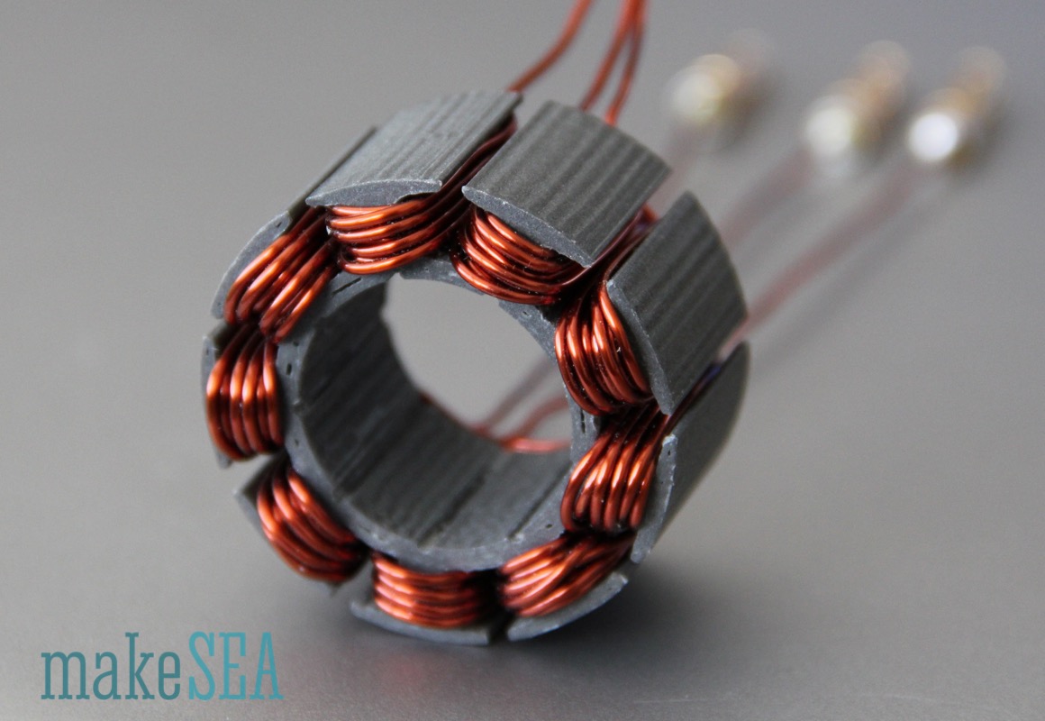
The initial design was similar to a regular brushless motor, which can be found in many RC-toys. The design has 9 teeth and 12 magnets (9N12P). The stator has a diameter of 40mm and a height of 20mm. The slot between the teeth was big enough to fit 8 turns per tooth with 1mm thick copper wire. The 12 magnets in the rotor are 10mm wide, 2mm thick and 20mm long (needs to match with stator height).
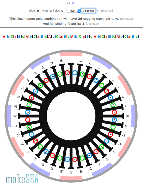
The stator winding scheme is very simple:
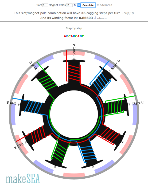
(thanks to http://www.bavaria-direct.co.za/ for the great online calculator)
Now it’s time to measure the basic characteristics of the motor by using it as a generator. A simple, well known method is using a drill press and a voltmeter. Since I’m even owning a scope, I’m using this instrument to measure the RPM and the voltage:
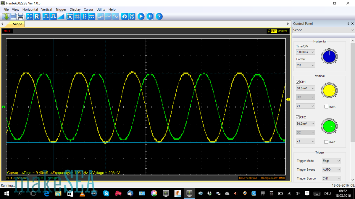
Only 0.1V amplitude at 1’000 RPM is not ideal. OK, it’s not nothing, but it roughly means Kv = 10’000 RPM / V or in other words: when running it as motor on a 12V battery, the motor would make 120’000 RPM. No chance, that the rotor survives the centrifugal forces at this speed. It would explode, and the magnets will fly away like projectiles. Very dangerous!
Nevertheless I gave it a try, connected the 3 wires of the motor to the ESC of my child’s RC car, which runs with an 8V battery. Very gently using the throttle … nothing happens. The motor makes some beeps, it only does some minor jerky movements. Full throttle! Still nothing - only the beeps were a bit louder.
The explanations, why it doesn’t run is simple (at least for me as an Electrical Engineer).
First you need to know, how an ESC works: In order to make the motor turn, the ESC needs to power the 3 wires (the coils) in the right sequence and this generates a rotating magnetic field. The permanent magnets in the rotor will follow this rotation. If the timing is too fast, the rotor will “slip”, and not follow. In order to not slip, the ESC will wait with powering the next coil, until the rotor has turned to the appropriate angle. But how does the ESC know, where the rotor currently is? The answer is “back EMF” - only two coils are powered, and the third coil is working as a generator (similar as described above for measuring Kv). If the generated electrical signal fulfills certain criteria, the ESC switches the powered coils, and uses another coil as generator, etc.
Problem: with zero RPM, the generated voltage is also zero, and the ESC can’t measure a signal! In order to start from zero, the ESC starts “blindly” by powering the coils at a fixed, very low speed. The rotor hopefully follows, and as soon as the generated signal is strong enough, the ESC increases the speed in a well controlled manner.
Our 3d-printed motor has the problem, that Kv is by far too high: the generated Voltage is too little (ESC fails to detect a signal), magnetic forces are too little and the inertia of the rotor (heavy magnets) is too big, it can’t accelerate fast enough. Finally the motor can’t follow the “blind” startup sequence of the ESC. Even a manual impulse doesn’t help.
Conclusion: Fail!
To be clear: the design doesn’t have a fundamental bug. If the coils are connected and disconnected manually to a power source in the right sequence, the rotor follows, and rotates step-by-step. If the ESC had an even more conservative startup-procedure, it probably worked. But a special ESC isn’t my goal - the motor should run with a common ESC!
So it’s clear, that the Kv-value needs to be dramatically reduced. Or in other words, the generated voltage needs to increase a lot. The result will be a lower RPM (lower centrifugal forces) which goes along with a higher torque. Finally the ESC will be able to sense the signal of the un-powered coil.
These modifications will have the desired effect:
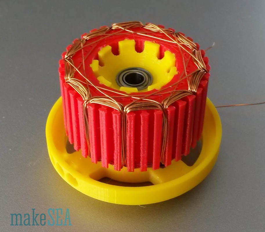
In order to test the effect of more turns closer at the magnets, I’ve re-designed the stator. The wire diameter needed to be decreased to 0.35mm, because more turns require more space, and space isn’t available. The new stator has 36 slots (4 times more). Teeth are only ⅓ as long as the initial stator teeth (wires closed at magnet). Winding scheme is basically simple:
The new stator was initially printed with regular PETG (not ferromagnetic), and onlyone phase was wound (with 10 turns per tooth, 1.2 times more compared with prior design). This is sufficient to check, if the new design and the windings have the desired effect.
The stator height is still 20mm in order to reuse the existing rotor with the 2mm magnets. The overall improvement factor was theoretically 4*3*1.2 = 14.4 divided by an unknown factor due to the non-ferromagnetic PETG. It’s time for the trouth - connect to drill, and measure with scope:
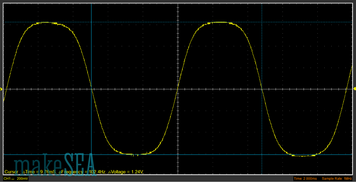
The effect is clearly visible: 1V amplitude at 1’000 ROM, roughly Kv 1’000. Numbers would be even better if the magnetic PLA was used. Great! :-) … And we can estimate that the magnetic PLA amplifies the magnetic field by a factor around 1.4.
Only drawback is the cross-section of the copper wire. The resistance of a single coil is 1.3 Ohm. That’s a killer: at 3A load, the power loss over the coil is 12W, which finally results into heat. With all 3 coils in action, the motor produces heat with 36W. That’s like the power of an average soldering iron. Too much for a PLA core! The motor would melt.
Anyway, the actions had the right effect, we’re on the right track.
The final changes affect the whole motor: 3mm thick magnets (maybe 1.5 times stronger), 30mm long magnets (higher stator, 1.5 times longer), and use magnetic PLA for the stator (1.4 times better). With 0.67mm copper wire diameter, it is possible to make only 3 turns per tooth (3.3 times worse). The reduced number of turns is hopefully compensated by the other improvements. Kv of this motor will theoretically change by a factor of 1.5*1.5*1.4/3.3 = 0.95
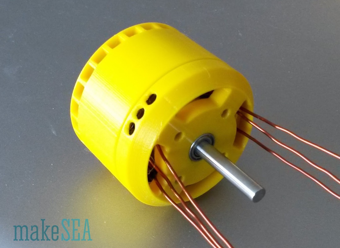
In-deed the final changes were the successful formula. The first 3d-printed brushless motor, running on a common ESC was born. And the motor deserves it’s name as a motor: with 35W and 60% efficiency it has enough power to drive a demanding application.
The motor is named “makeSEA Model A001” and described in a separate article.