
Idea: Wind Turbine Project
by Christoph Laimer
The goal of this project is 3D-printing a fully functional Wind Turbine (WT) at small scale, using commonly available printing technologies and materials. The WT should be able to generate electrical energy in order to supply a small consumer component.
One could argue, that a solar panel already does the job much more effective. The main motivation of this project isn’t the actual resolution of an energy problem for a small consumer electronics device, but the exploration of available technologies and their application. The project should be inspiring and motivating for many people, and to some degree it should be educating how to deal with energy resources.
The Wind Turbine should be an open, modular design. Specifications and vision of the Turbine itself can be iteratively enhanced or changed.
Initial Specification
- Mountable on balcony, exposed to wind and weather
- Stores generated power in a Super Capacitor
- Goal: 5m/s wind speed should be sufficient to charge the capacitor.
- Blades are semi-transparent with integrated LEDs
- Microcontroller “writes” patterns with rotating blades (like “Blinky POV”)
- Wind powered weather station? …
These requirements allow to explore aerodynamics, electricity, programming, 3D-design, 3D-printing, material science, mechanics, physics, etc.
Implementation Concept
- Blades, Hub, Housing, and Fin are fully 3D-printable. Multiple parts screwed together.
- Hub and Housing are big enough to embed electronic components.
- Propeller thickness for 3mm LEDs. Maybe the LED wires are printable with conductive PLA?
- Knowing that a brushless motor is 3D-printable, also the generator for the WT is 3D-printable - a derivation from the brushless motor with modified coils. Little amount of wind means low RPM and low generator voltage: therefore generator windings with lots of turns.
- Simple diode rectifier and a voltage stabilizer is used as charging controller.
- Arduino located in Hub, powered by 2 wires (shaft + sliding contact)
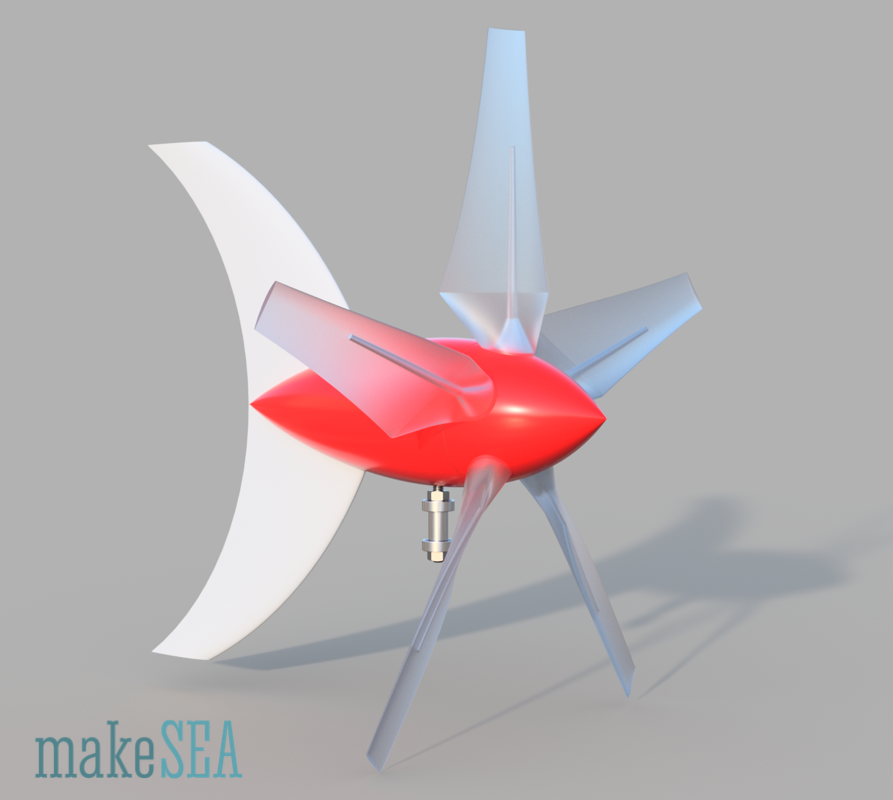
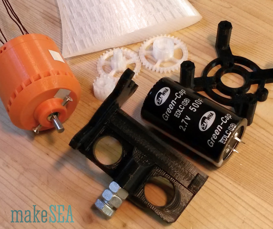
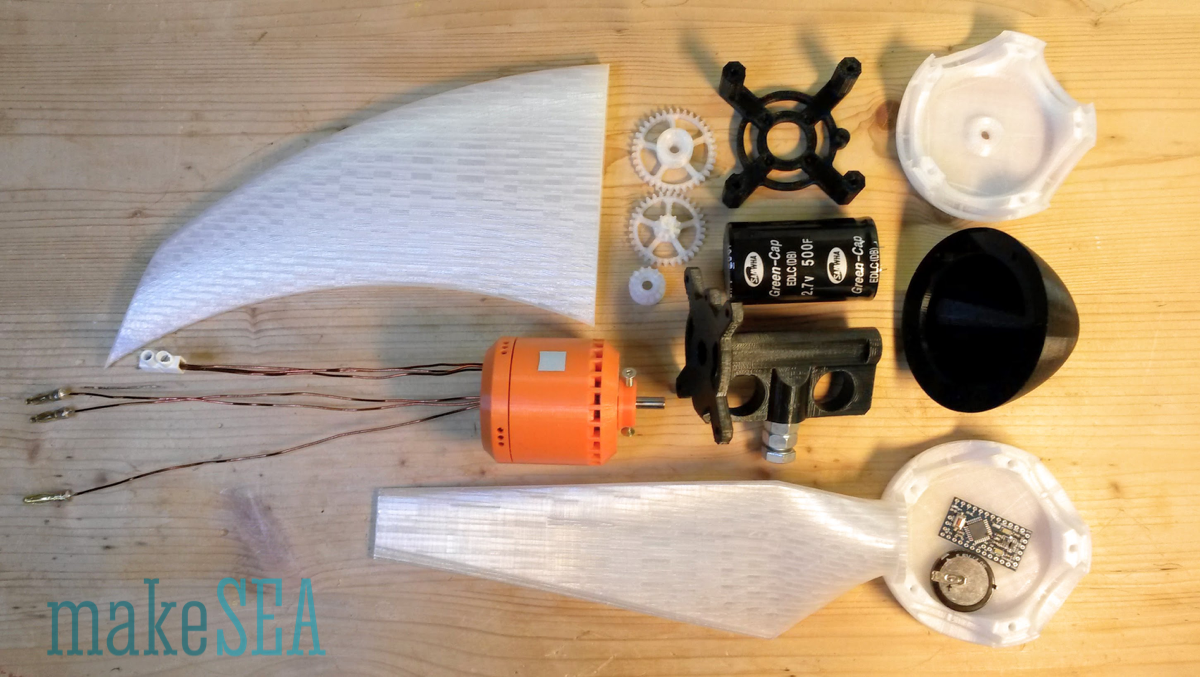
Draft Components:
Design Inspiration from Former Project
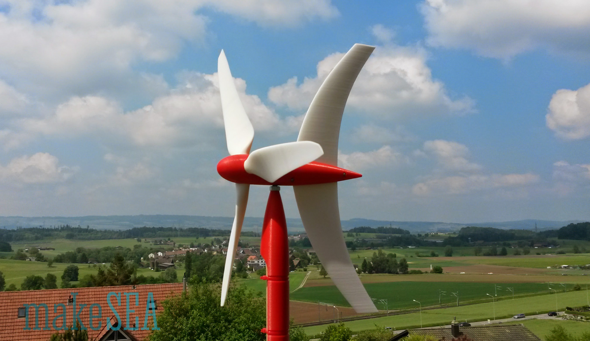
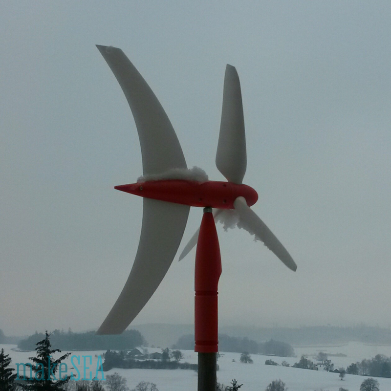
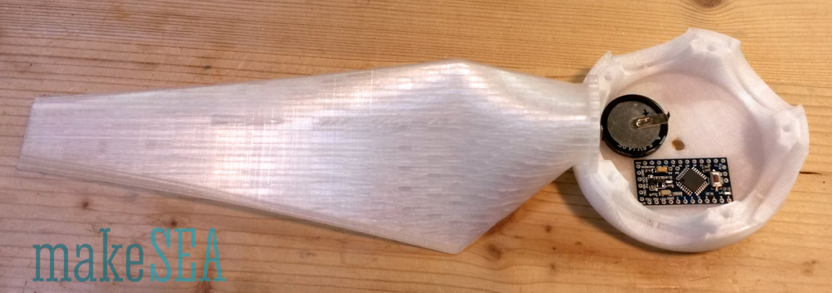
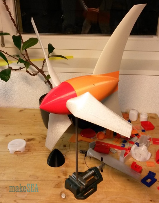
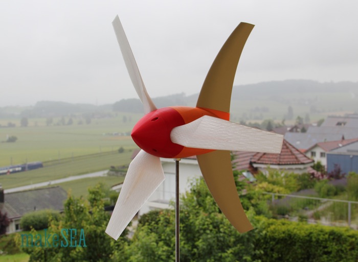
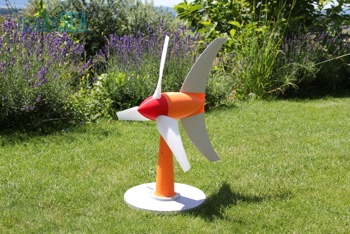
This is my “old” windmill. It’s designed with Blender, and printed with PLA. It’s now a full year exposed to high and low temperatures, rain and sun, storm, snow and hail, and it’s still working. Propeller diameter is approximately 40 cm, the propeller shaft diameter is 3 mm and it has 2 ball bearings. The vertical axis consists of a 8 mm bolt, and also has two ball bearings.
This design seems to be very robust. It only needs to be “inflated” in order to house the generator, the capacitor, the microcontroller, and the LEDs.
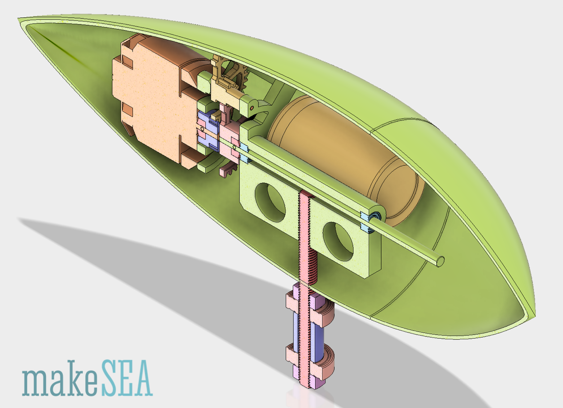
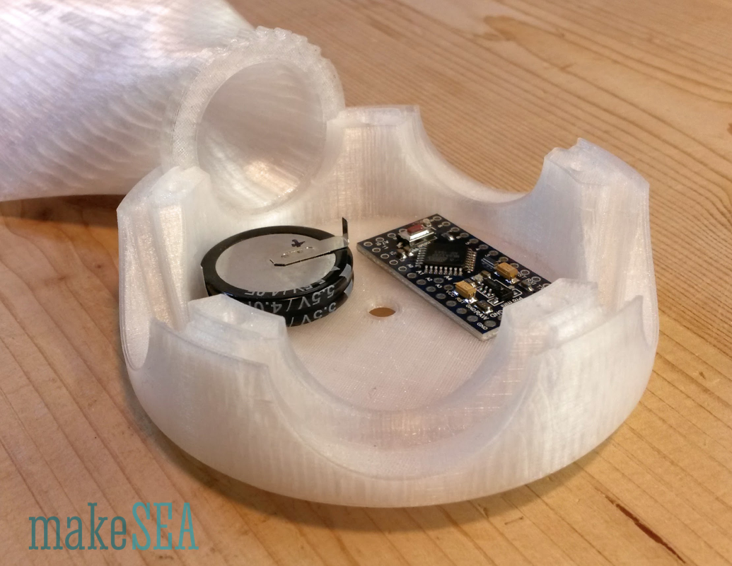
The main housing needs to have space for a generator (same size as the 3d-printed brushless motor, 55 mm diameter, 55 mm length). In addition there needs to be space for 2 Super Capacitors (60 mm height, 35 mm diameter, 2.7 V, 500 F). The hub needs to be big enough for an Arduino Pro Mini and also a good capacitor (makes life simpler to construct a “crappy” sliding contact with a simple washer). In addition there is a small Hall-sensor for synchronizing the flashing LED’s with the propeller rotation. The propeller blades will have a cavity, which allows to insert some LEDs. The design of the hub has a variable parameter with the number of blades. 3, 4, of 5 blades work well. Two blades are not ideal because of extremely unevenly high gyroscopic forces, if wind direction changes - with 3 blades the gyro-forces are also high, but much more even. 6 blades overlap with the selected hub dimensions.
The whole construction needs to be as good as possible water-tight. Potentially it’s not as tight while the Wind Turbine is being developed, but the design should have provident grooves, which could be sealed with glue (when it’s finished).
The Generator
We’d like that the WT is charging the capacitor at 5 m/s wind speed:
| Wind Speed | 5 | m/s |
| 18 | km/h | |
| 11.25 | mph | |
| Propeller Diameter | 500 | mm |
| Propeller Pitch | 500 | mm |
| Propeller Speed | 600 | RPM |
| Minimum Charging Voltage | 7 | V |
| Generator Kv for Charging | 86 | RPM / V |
Earlier measurements of Kv from the brushless motor are very useful to design the generator:

There are 4 different versions with different materials, different stator height, and different number of turns.
| Generator Version (brushless Motor) | v0 | v1a | v1b | v2 | |
| Generator Kv | 10'400 | 1'004 | 1'006 | 1'344 | RPM/V |
| Voltage at nominal Wind Speed | 0.06 | 0.60 | 0.60 | 0.45 | V |
| Generator Speed needed for Charging | 72'800 | 7'028 | 7'042 | 9'408 | RPM |
| Wind Speed needed for Charging | 2'184 | 211 | 211 | 282 | km/h |
| Gear Transmission Ratio for Charging | 121 | 12 | 12 | 16 |
None of these versions is suitable to be directly driven by the propeller - the generated voltage is too low. This conclusion is not really surprising, as the motor was optimized towards high power (30-50W) and low voltage (7V). The result is low resistance and high RPM.
For powering a microcontroller and a few LEDs there is not much power needed. 10 LEDs at 10mA and a Microcontroller at 5V require roughly 0.5W. A small WT-propeller at low wind speeds doesn’t provide much power anyway. So we can afford a generator wiring with relative high resistance - i.e. coils with a small copper wire diameter and many turns.
Potentially version “v1b” (the first working version of the brushless motor) can be re-wired with 0.2mm wire instead of 0.67mm wire. An experiment needs to be done in order to know the maximum possible number of turns.
Transmission
Even though the stator can have significantly more turns (higher induced voltage / resp. lower Kv), it’s probably not sufficient to charge the capacitor at 5 m/s wind speed. Probably a test without transmission is useful to be performed initially. However, this is an idea, how to implement a transmission increasing the RPM:
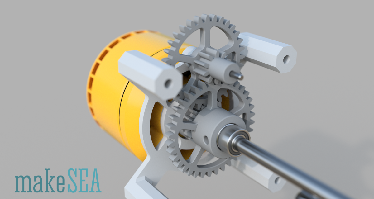
The propeller shaft will have 5 mm diameter and 2 ball bearings, and the generator is mounted coaxial with the propeller shaft. This allows direct driving the generator as an alternative solution (by simply using a longer shaft, and leaving away one ball bearing from the generator and another from the main propeller shaft).
Simple 3 Phase Rectifier/Charger
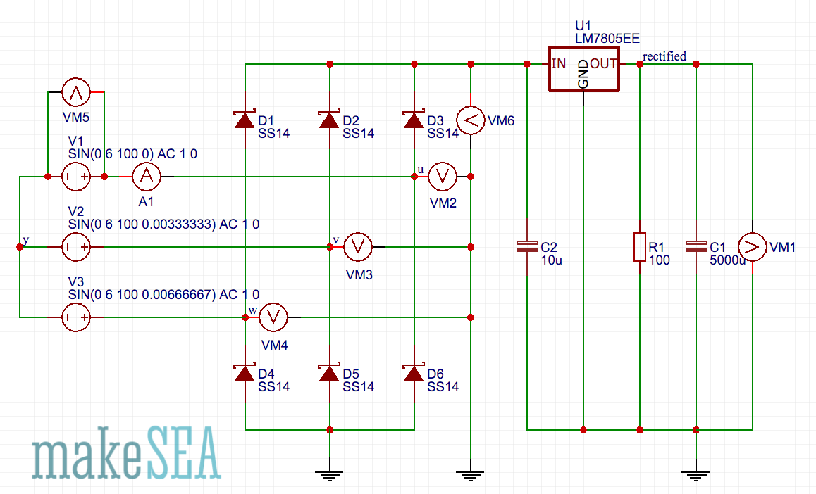
Circuit simulation using 6 diodes and a capacitor in order to transform AC to DC. The Voltage regulator limits the charging of the big Super Capacitor C1. Required AC voltage is roughly 7V. The frequency (RPM) doesn’t matter. The resistance of the Generator coils will limit the charging current (not considered in this simulation).
3D-Printing
Printing the propeller and the fin with transparent PETG, one shell layer, 15% infill. This works well. The size of the objects is at the maximum of the build volume for an Ultimaker 2. This is too big for the Replicator 2x. I’ve no idea, how big the blades need to be in order to overcome friction and generator magnet clogging - so the biggest possible size for the first prototype is on the safe side. Still can make things smaller, when optimizing the Wind Turbine.
Things that had to be Solved:
- Figure out, if a geared transmission is needed or not (has a big influence on the simplicity of the design): re-wire a brushless motor and measure the generated voltage.
- Properly design the internal structure of the house, holding the capacitor, the propeller shaft, the generator, the vertical rotation axis (wind direction).
- Find a good design for a water-proved housing shell with the tail-fin attached.
- Design the sliding connection from housing to hub (+5V), design electrical connection through ball bearing and propeller shaft collar (GND).
- Design to hold microcontroller, Hub-capacitor, and Hall sensor with magnet in place.
Implementation: The windpowerWriter
by Christoph Laimer

windpowerWriter 3D printed wind turbine/generator
(see also, Brushless Motor)
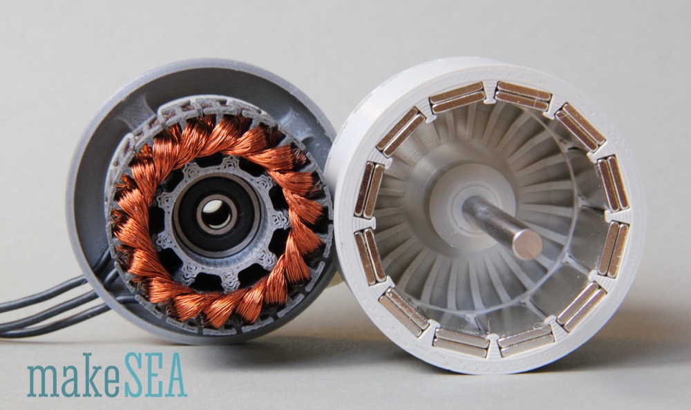
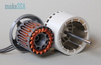
Generator
The generator is based on the brushless motor v2 (makeSEA Model A001.1). The stator of this motor has special heads on its teeth, which guide the wires and simplify the manual work. Because the turbine should charge the capacitor already at low wind speeds, and because it should work with some very simple electronics, it’s required that the generator produces a relative high voltage at low rotation speeds (low value of Kv). A common solution are stator-coils with many turns (and therefore thin wires). In addition to the turns it helps to have stronger magnets (on rotor). The ambitious goal is a Kv value less than 100 RPM/V.
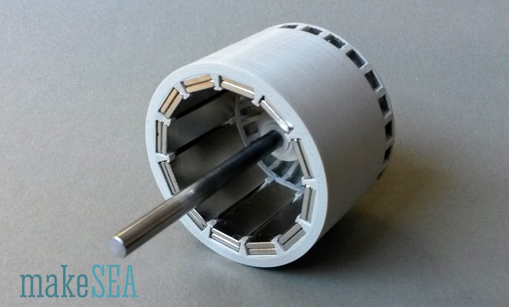
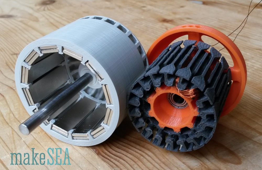
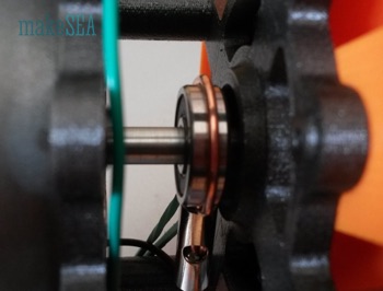
Rotor
Because I had many spare magnets in various dimensions (experiments from designing the brushless motor), I reused the 2mm thick magnets. Actually they are 1.85mm thick, and a stack of 2 magnets (3.70mm) are only a little bit thicker than the single 3mm magnets (2.76mm). Together they are also a bit stronger (maybe 10-20%). The win isn’t really big, so the rotor of the brushless motor could also be used, but since the magnet thickness is a simple parameter in my Fusion 360 design, it was easy to change it and 3d-print a new rotor.
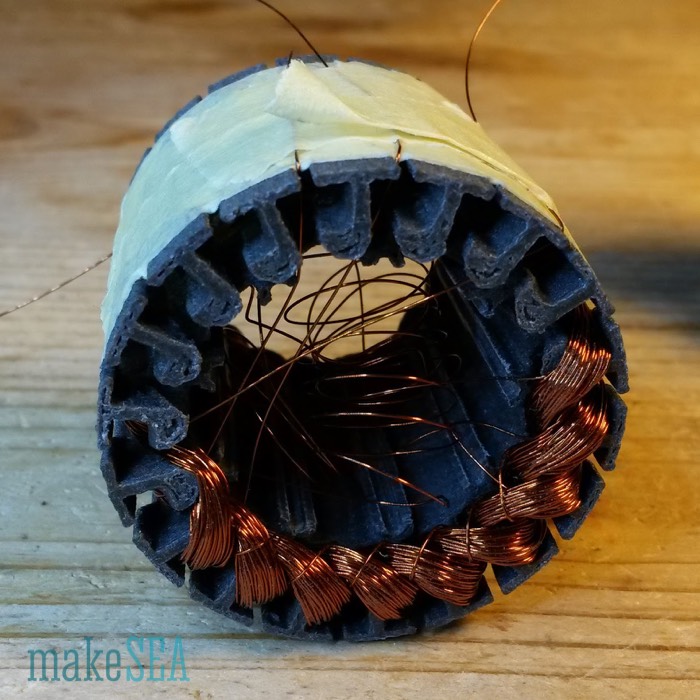
Stator
The concept of the generator stator is based on the earlier experiments for the brushless motor. The very first version had a Kv by far too high, and I needed to increase the number of turns for the coils. The result then was Kv = 1’000 RPM/V. That’s still 10 times too high compared with the goal.
However the subsequent design changes of the stator for the brushless motor allowed to decrease the number of turns (in favor for a larger cross-section and higher currents) while keeping the Kv almost unchanged. This means the Kv could be clearly reduced with the large number of turns and the thinner wire. Hence I reused the unchanged design of the stator from Model A001.1 as the stator for the generator. Initially I only wound a single coil, and measured with the drill and the scope its properties.
| Wire Diameter | 0.21 | mm |
| Turns per Coil | 63 |
|
| Wire Length per Coil | 6’150 | mm |
| Amplitude single Coil (measured) | 1.325 | V |
| Rotation Speed (measured) | 1’054 | RPM |
| Kv (calculated) | 80.5 | RPM / V |
These results were very promising, so I continued with the stator winding (with 64 turns per coil, because 64 is a nicer number than 63). From the first coil, I could measure the weight of the used copper (knowing also the weight of the empty stator). It was 2.14 grammes. The complete generator has 6 coils per phase. For each of the 3 phases the copper wired needed to be wound on a temporary spool. Hence 6 times 2.14g = 6.84g copper wire per spool. Wrong! How embarrassing - I realized my calculation mistake in the middle of the winding work at 2:00am. I had to extend and solder these flimsy wires in the middle of the night. The finally needed copper per phase weights exactly 10.31g (measured). Without calculation mistake, the prepared spools would have been well suitable.
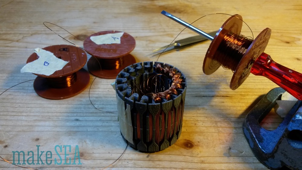
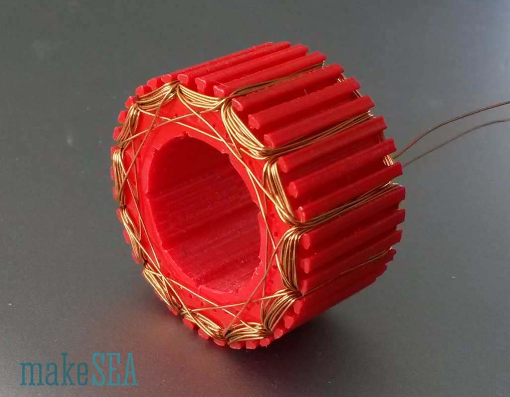
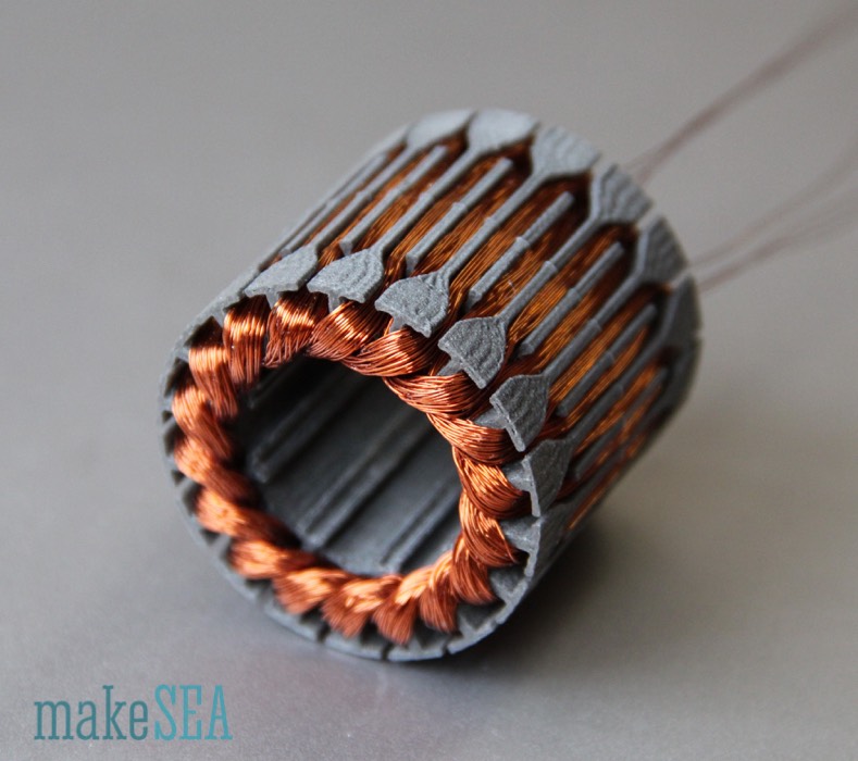
The whole winding was really a lot of work - I needed much more than 12 hours (I didn’t really count the hours - it was a rainy weekend anyway).1 The very last coil was especially painful, because it needed to go beneath the first coil. So I was using a sewing needle, and needed to pull almost 8 meters of this tangling thin wire 64 times through the gap between stator core and coil #1. But the result looked very beautiful - it actually had to look beautiful, because the expected performance was very promising.
1. 64 turns is a lot to count without making a mistake, so I would recommend finding an efficient way of marking how many turns you have made. It will be very disappointing when you get to testing the generator and having it not work because the turns are not balanced. -D. Hartley
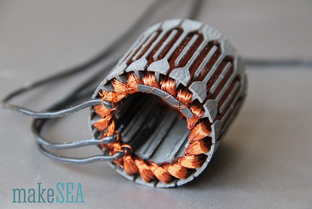
The problem with this stator: the thin wires appeared very prone to break, if the generator was carried around, connected and disconnected again and again for my tests. So I decided to finally connect flexible and durable copper wires for the external connection. The starts of the 3 phases A, B, and C are soldered together to a single point, isolated with heat shrink tube, and fixed with some spare copper wire at the other coils. Each of the 3 ends is then soldered to an individual flexible cable, and also isolated with heat shrink tube.2 The wiring scheme is named “star” (or “Y”) connection. See Wikipedia for more information: https://en.wikipedia.org/wiki/Brushless_DC_electric_motor#Variations_in_construction
2. Doing this is recommended but not mandatory, because the generator will work with and without the previous recommendations, but adding the flexible wire saved a lot of headaches. D. Hartley
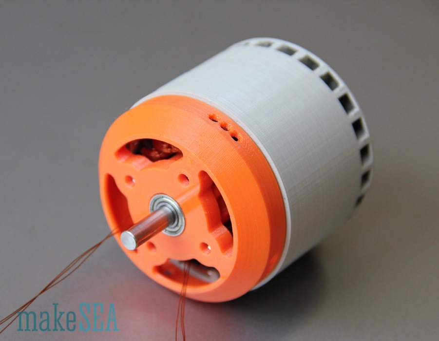
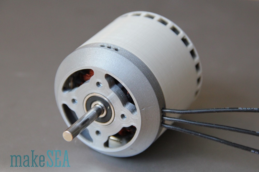
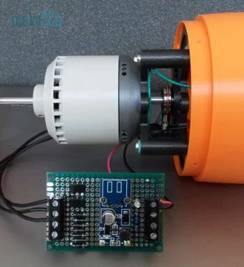
Also the orange stator shield was a bit too small for the larger rotor, and I wanted to reuse it anyway for the brushless motor. So I decided to 3d-print the shield with a slightly larger outer diameter and with a different, more technical color. I also had other ball bearings which I wanted to try, and finally these changes were a good test, if my parametric Fusion 360 design was working.3
3. Make sure the bearings fits seamlessly into stator, and the rod you use fits almost perfectly into the bearings or the generator will not perform well or not perform at all. -D. Hartley
Here is the final result:
The finished stator has 3 * 6 * 64 = 1’152 turns. With 36 teeth it’s 32 turns per tooth. The generator is ready for extensive measurements and tough tests.
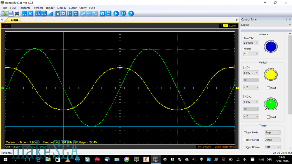
Measurements
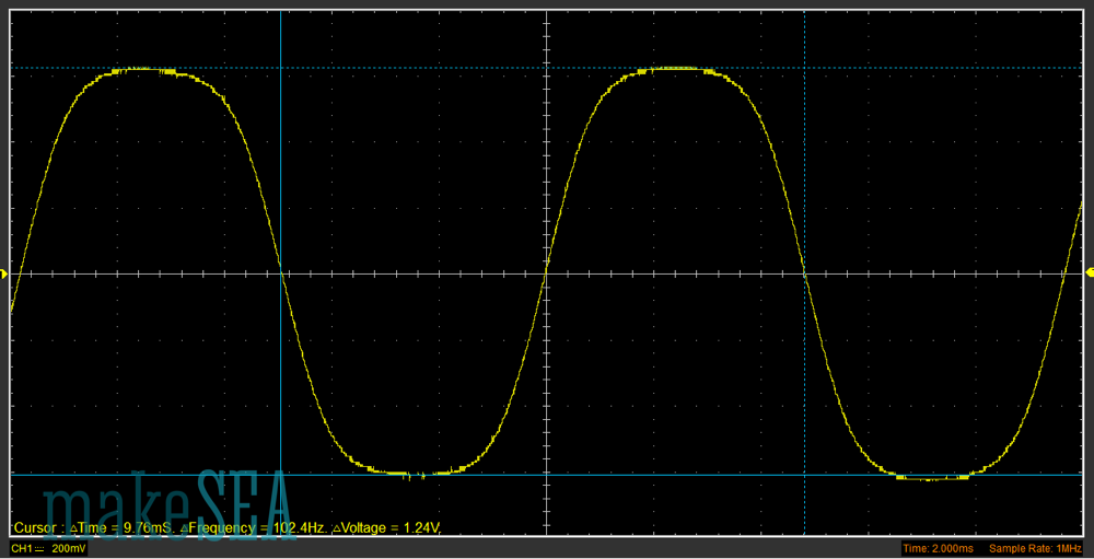
The initial measurement of Kv was done in the same way as before with drill and scope. The calculated values could be confirmed. The measured amplitude was 13.7 V and frequency was 101 Hz. Mission seems accomplished ...
Here are the basic measurements and characteristics of the generator:
| Resistance per Phase | 19.50 | Ohm |
| Inductance per Phase (may be relevant for the charger) | 650 | mH |
| Kv | 77.6 | RPM / V |
| Nominal Speed (5 m/s wind, 500 mm propeller pitch) | 600 | RPM |
| Nominal Voltage (at nominal speed) | 8.14 | V |
Of course the generator works as well with higher RPM (with storm-winds), but so far the generator behavior at low wind speeds is more important.
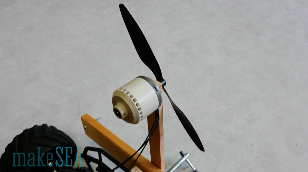
The Kv figure doesn’t tell much about the real efficiency as a generator, when it’s charging a big capacitor (or a battery). Because I didn’t have an appropriate / measurable load ready for this test, I was using this generator as a motor. Load means, that there is some power produced - Voltage and Current in the copper wires needs to be different than zero. Motor and generator are reciprocal anyway. As load I used my well known propeller with 10 inch diameter and 4.5 inch pitch. It wasn’t surprising, that the motor doesn’t rotate very fast, if the 6 cell NiMH battery with 7.2V was used. In fact the motor didn’t even start rotating on it’s own, but with a gentle kick by hand it worked. The problem with getting started isn’t the motor, but the combination with the ESC and the battery. Compared with the regular motor, the system behaves as if the RC car was driven with only a single and almost empty cell NiMH. So I have done these tests also with another ESC from a RC car, which runs at 6S LiPo (roughly 24V). With the higher voltage (and the other ESC) the motor could start spinning without issues.
Propeller constante: 1.63E-09 [N*m/RPM^2] … the number was calculated from previous measurements with the brushless motor at much higher RPM. This number is now very useful to calculate the power at low rotation speeds, because it wasn’t possible to measure the torque (the resolution of my scale is too bad).
|
| 6 cell NiMH | 6S LiPO |
|
| Battery Voltage | 7.40 | 22.80 | V |
| Speed (no load) | 556 | 1’730 | rpm |
| Battery Current I0 (no load) | 0.035 | 0.02 | A |
| Speed (with Propeller) | 545 | 1’615 | rpm |
| Battery Current (with propeller) | 0.04 | 0.055 | A |
| Battery Power (with propeller) | 0.3 | 1.25 | W |
| Shaft Power (with propeller) | 0.03 | 0.72 | W |
| Efficiency (with propeller) | 9% | 57% |
|
There is a nice online calculator on http://www.bavaria-direct.co.za/constants/ which can compute the efficiency based on a few fundamental motor constants (Voltage, Current, I0, Kv, Rm).
| Efficiency (bavaria calculator) | n.a. | 56% |
|
| Efficiency Maximum at 0.1 A (bavaria calculator) | 32% | 70% |
|
The similarity of the calculated efficiency and the measured efficiency with 6S LiPo is amazing. It means that the ESC doesn't have much losses (no wonder - it’s designed for 100A continuous load). The result for the lower voltage isn’t reliable: the measurements of the current are at the limit of the resolution of my instruments, and if the ESC had losses of only 1W, it would distort the results a lot.
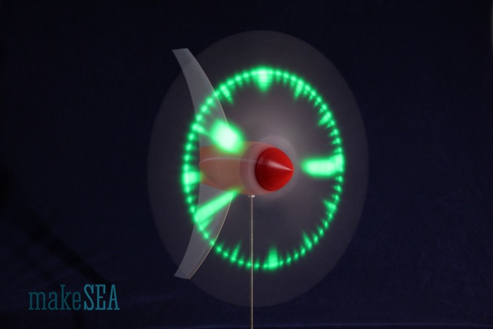
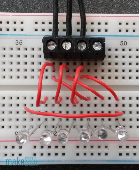
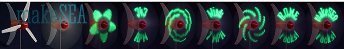
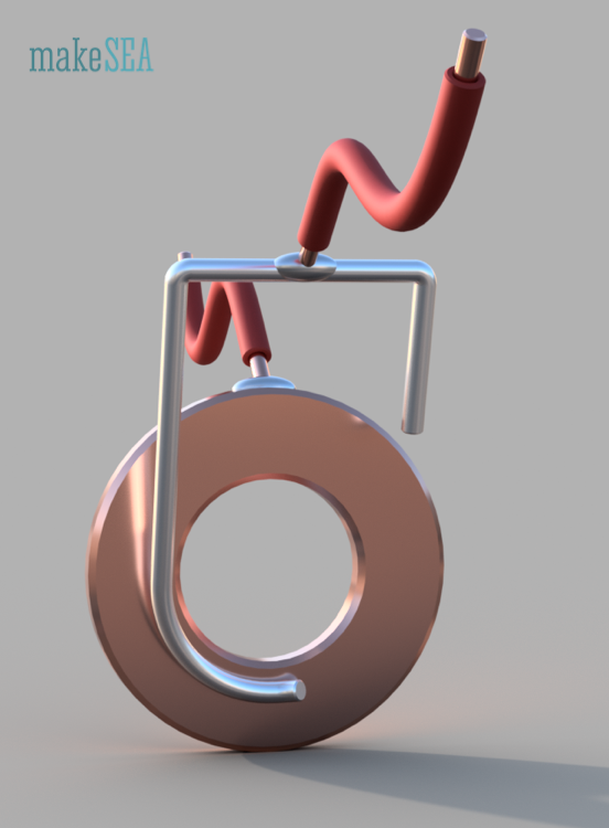
Finally I’ve done a last measurement with 6 red LEDs as a simple load. A red LED lights up very bright already at 1.8V. With the 3 phase generator it is possible to make a knight-rider flashing light.
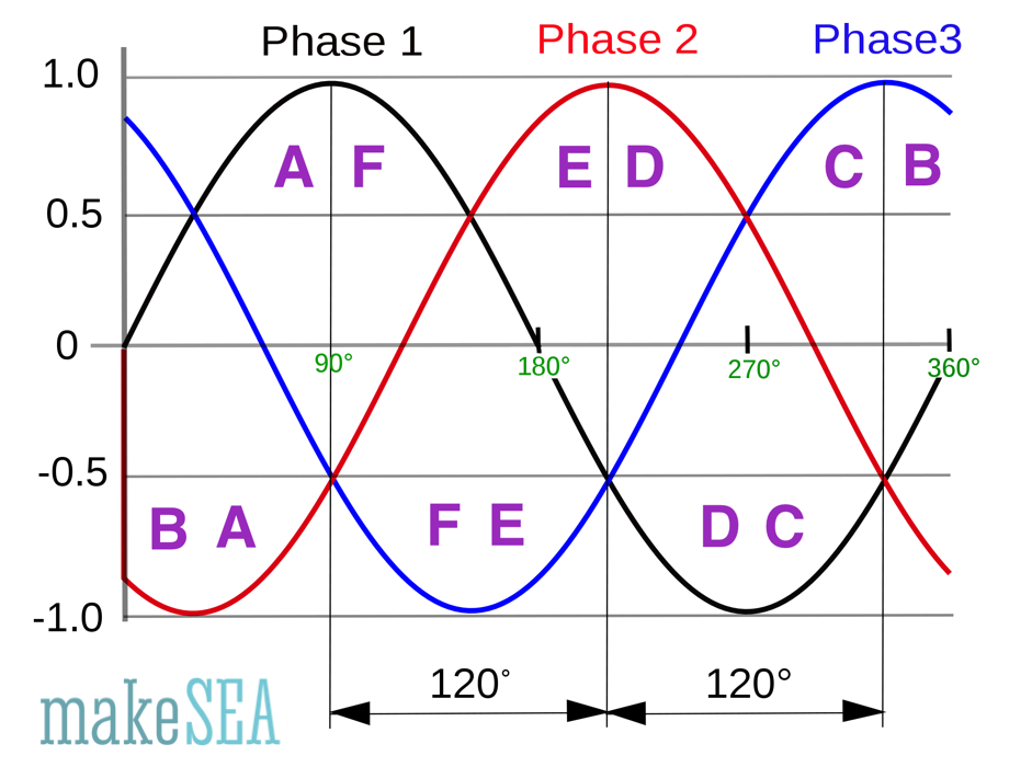
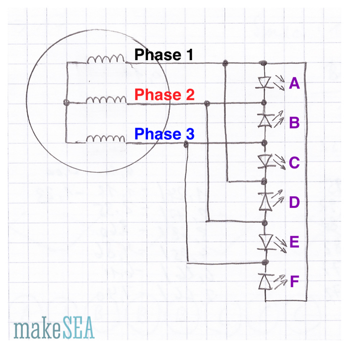
See Wikipedia for more info about the 3 phase signal: https://en.wikipedia.org/wiki/Three-phase. Our generator produces such a signal, whereas frequency and amplitude depend on the rotation speed. In the circuit LED A lights up, if the voltage of Phase 1 (black) is 1.8V higher than the voltage of Phase 2 (red). LED B lights up, if Phase 3 (blue) is higher than Phase 2 (red), etc. That’s a fun circuit - the LEDs light up in sequence, whereas 2 or 3 LED are on at the same time (e.g. at 180° LEDs D, E, and F are lit and the rest is dark).
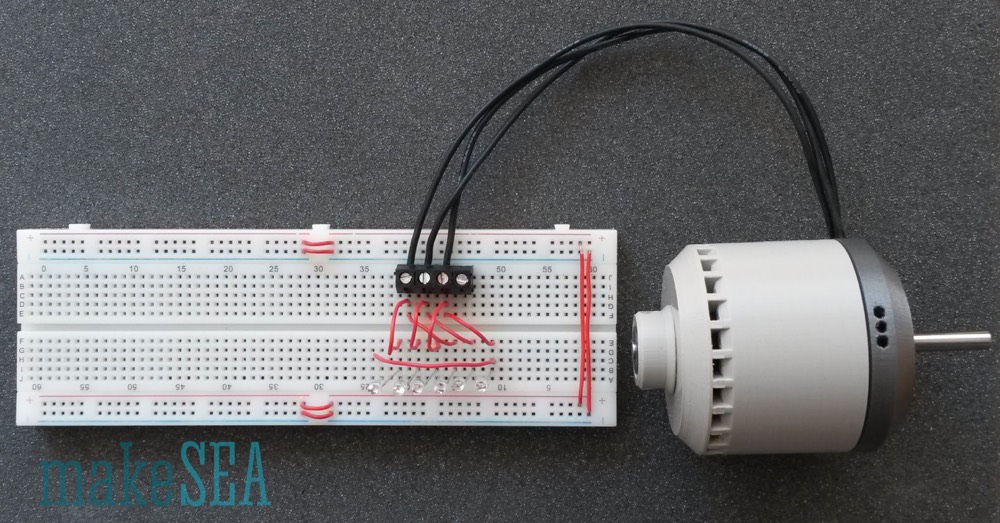
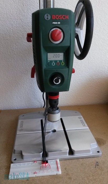
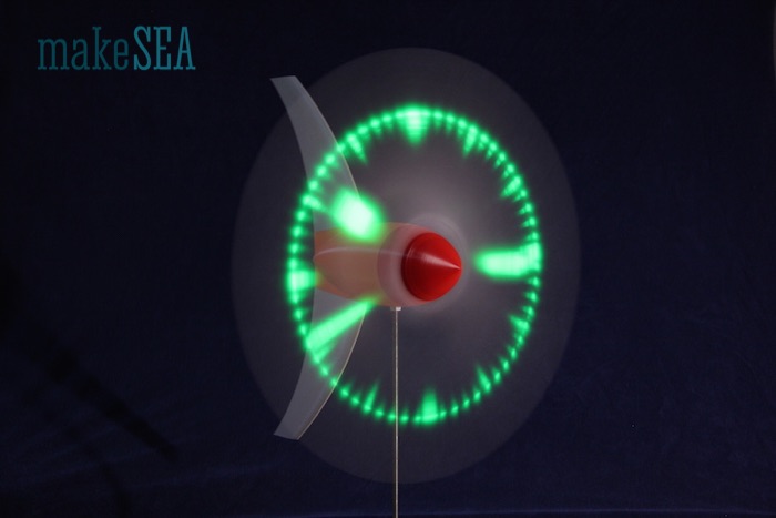
The LEDs light up already, if I manually turn the rotor with very little effort. Anyway I’ve fixed the generator in my drill-press rotating at only 200 RPM and took a photo while moving my camera across the LED-bar. With the camera exposure time, light during a period of several milliseconds is collected. The blurred image shows, how the individual LEDs light up in serial sequence due to the 120° shifted phases of the generator (if they would light up all at the same time, the LEDs would appear horizontally arranged). Hello Blinky! ...

The LEDs in this circuit theoretically should be protected by a resistor. They would be damaged at higher voltages. I was luckily able to contain myself to crank up the RPM of the drill press. Blowing up an LED isn’t very spectacular - it gets hot and the light gets darker until if finally extinguishes. With some luck there is a little bit of smoke ...
Conclusion
I expect that this generator will perform very well at low RPM. The output power will be sufficient for a microcontroller and some LEDs at 5 m/s wind speed. The maximum charging power is unclear. Due to the huge manual winding effort, I would consider to do less turns and use some more sophisticated electronics (with integrated step-up converter).
Rectifier/Charger v0
The thing I’m going to create here is a very simplistic rectifier / charger with inferior efficiency. The whole Wind Turbine is quite a complex system. It makes sense to get all the components basically working, and then improve the weakest element. So I decided to build a 3-phase rectifier with 6 regular diodes.
Circuit Scheme
Actually I could have drawn this simple circuit by hand, but I found a great online tool https://easyeda.com/, which also has nice simulation features included. The use is very intuitive, and it’s for free - it only costs, if you order a finished PCB.
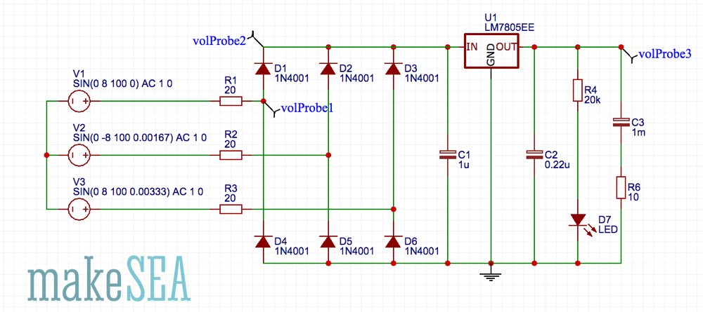
The generator is modeled with 3 AC voltage sources at 8 V amplitude and 100 Hz frequency. For the internal resistance of the generator, there are 3 resistors with 20 Ohm. Large capacitors need to be carefully charged - especially a specific voltage must not be exceeded. For this reason I’ve added a common 5 V regulator, which requires C1 and C2 at it’s in- and output. The LED indicates, if there is voltage at the output. I’ve used a bright green low-power LED with a large resistor (20 kOhm). Basically it’s not useful to have such a permanent consumer-LED in a low power application, and maybe I’ll remove that LED, when the whole thing is working. In reality I’ll have a 500 F capacitor to store the energy, but for the current tests I needed something smaller which quicker indicates, if it’s working: the “big” charged capacitor in this test-circuit has a capacity of only 1 mF (500’000 times less).
The circuit has some basic flaws: The voltage regulator can handle input voltage up to 40 V. With strong winds, the generator can produce much more, and the regulator will probably blow up. The regulator also doesn’t have a heat-sink for cooling - with only a small load, it should survive. If the big capacitor is completely empty, and there are stronger winds, the charging current could be very high for a longer time. The relative high resistance of the generator coils will luckily limit the current (at 0.5A load the generator heats up with a rate of 30W). More power can’t be expected with small propeller blades. In this case it’s good to have inferior efficiency at the generator (which is well cooled), so it won’t burn anything else.
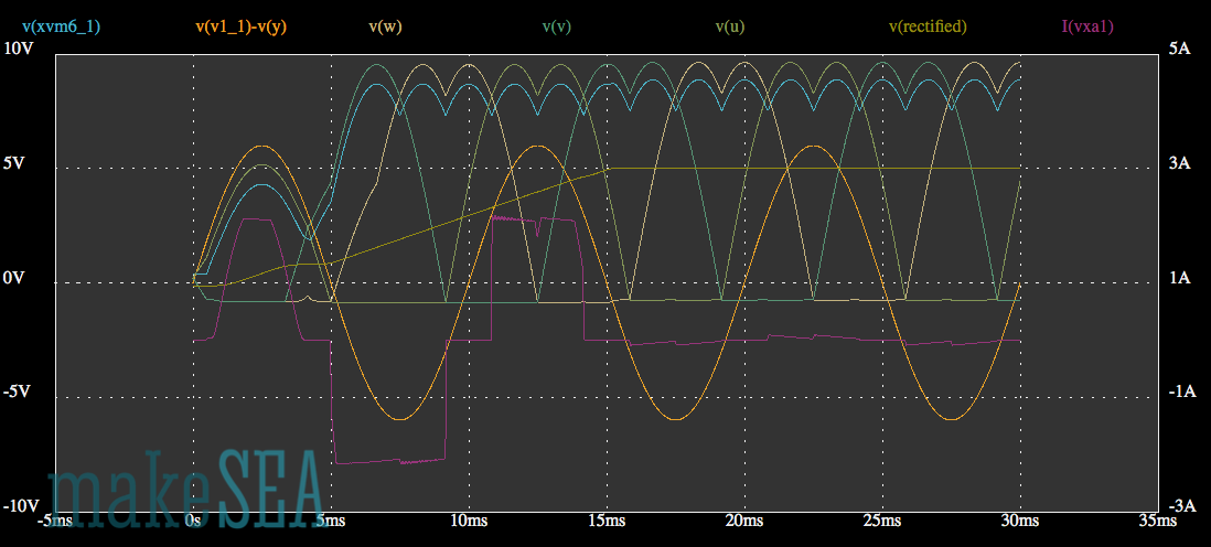
The simulation shows the voltage at 3 selected points (probes 1..3). First directly one of the generator wires (blue), then after the rectifier (red), and finally the output (yellow).

Initially all capacitors are not charged (0V). The output voltage (yellow) increases up to 5 V, and then it remains stable. While it’s increasing, the big capacitor is charged. During that time the voltage at the generator wires (blue) and the rectified voltage (red) have a small constant offset from the output voltage. This offset is roughly 1.5V and is caused by the voltage regulator, which draws as much as possible current from the generator and the generated voltage is lost inside the generator. As soon as the big capacitor is fully charged, the load decreases, and the generator voltage can further increase. It increases depending on the actual rotation speed, and can be calculated based on Kv.
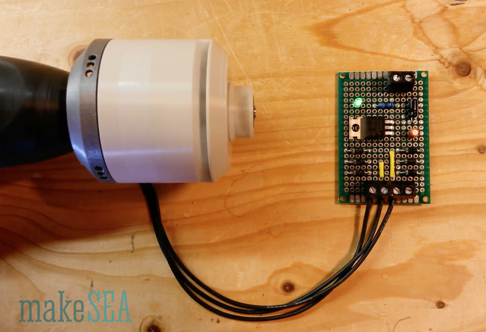
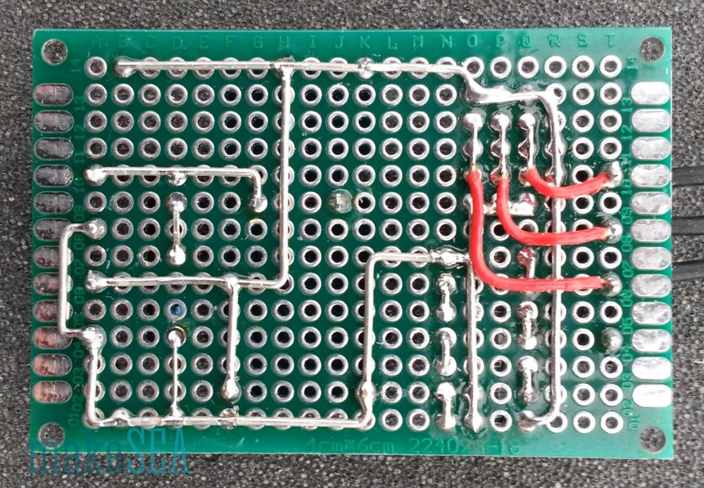
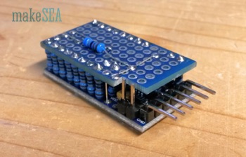
Soldering the PCB
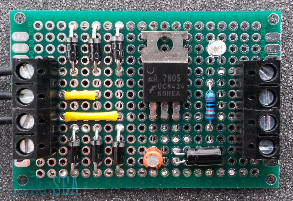
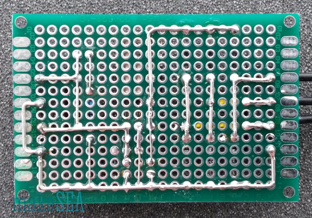
There is not much magic about soldering this circuit on a PCB. The images tell how it’s done. The components are all standard, and it would also work with different diodes or capacitors. The only thing I realized at the end: the fin of the voltage regulator needs to be isolated from the pads behind it, because I placed the rectified signal on the backside right beneath the fin (which is grounded). There would have been enough space for the rectified signal 2 grid units further right. No tragedy … time for testing:
Tests
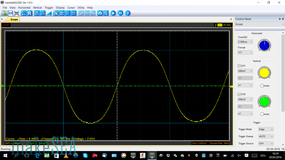
Guess the testing setup!? Yes - drill and scope:
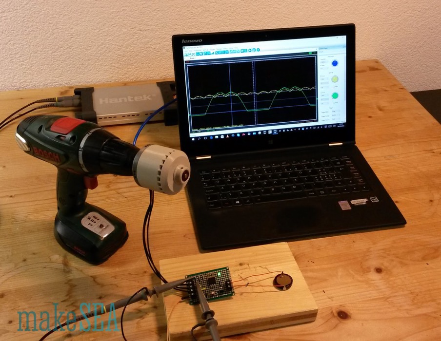
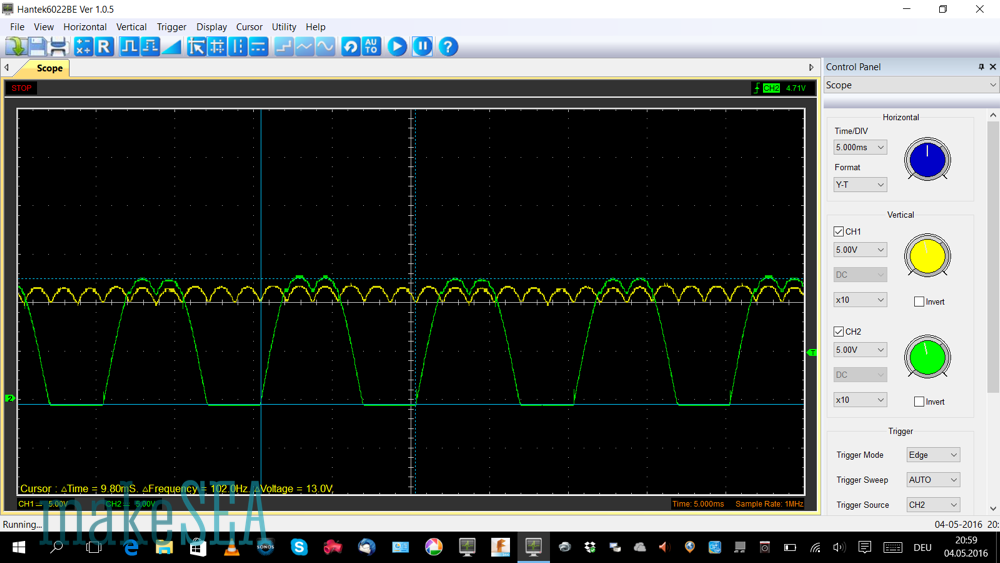
For the initial test I didn’t connect the big capacitor. Just the basic rectifier, with its LED and some smaller caps on-board. Hence the charging-process is very quick. I quickly pushed the drill throttle, but on the scope it’s still visible, that it needs some time until the drill rotates at final speed.
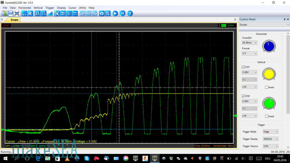
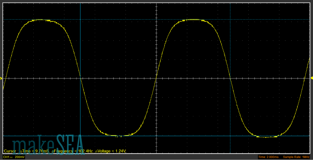
The green curve is one wire directly at the generator, the yellow curve is the output signal. The rectified signal is missing (my scope has only 2 channels). Differently to the simulation, the generator amplitude and frequency is ramping up until it has full speed. This makes it a bit difficult to interpret the charging process of the capacitor. Anyway, it’s visible that the voltage regulator does its job, and limits the output at 5V.
Then I’ve connected a 4F capacitor as a load to be charged. Charging takes much longer.
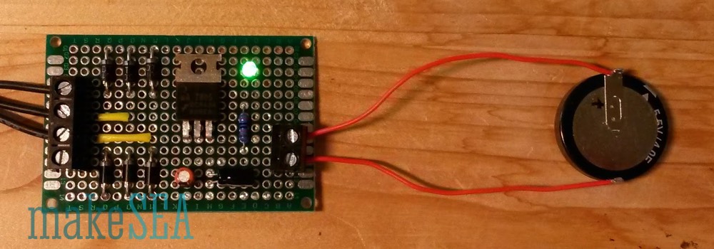
The ramp-up of the drill speed is no longer relevant, however it takes MUCH more time to observe the charging process. I’ve done two measurements: first snapshot when the capacitor isn’t charged, and the second snapshot 2 Minutes later, when the capacitor is full.
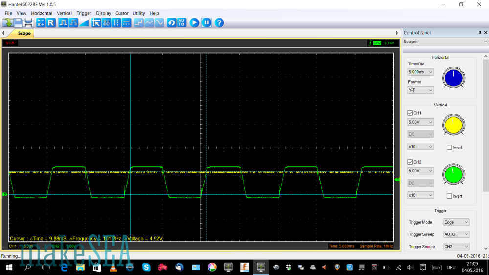
The green line shows again the voltage at the generator, but the yellow curve is now showing the rectified signal. The output stays stable at 5V anyway and isn’t displayed. The measurements remind on the simulation result: while the capacitor is being charged, the voltage is not much above the output signal (which is around 3-4 volts at that time). Later when the capacitor is fully charged the rectified voltage increases up to 12V.
Conclusion
The simple rectifier with 6 diodes and a 5V regulator is good enough for a first try. If electronics breaks due to overvoltage during a stronger storm, there is not much time and money lost. Maybe the propeller blades are even weaker … improvements can be done later.
Rectifier/Charger v1
The problem of the simplistic circuit v0: it only works, if the super caps are almost fully charged. If the super caps are only half loaded, it doesn’t work. And there is another problem, when there is too much wind.
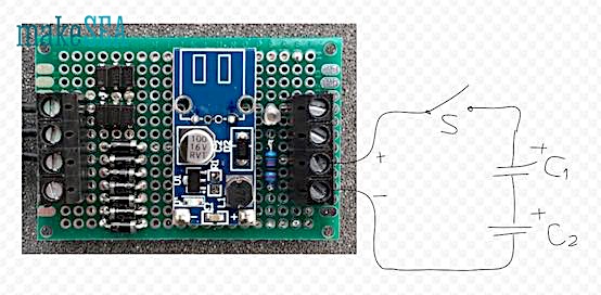
Step-up Converter and Passive Dump Load
As a solution a step-up converter can be used. There are very cheap and efficient modules available from Ebay or Aliexpress, which convert 0.9V (or even less) into 5.0V with very good efficiency. It’s basically designed to make an USB-charger from a single 1.5V AA battery.
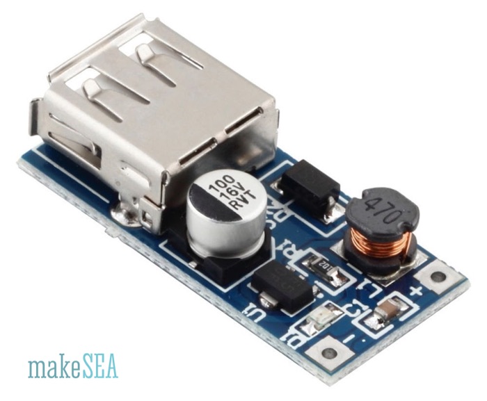
(image from ebay)
The modified circuit doesn’t look much different than the prior version, but it’s much more efficient.
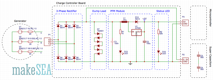
The 3-Phase rectifier converts the AC signal into a DC signal. It uses Schottky diodes, which have a lower voltage drop than regular diodes. With the DC signal the super caps are charged.
A simple dump-load made of 7 regular diodes limits the loading voltage to roughly 5V (the voltage drop of a single diode is roughly 0.7V). 6V => 275mA, 5V => 20mA, 4V => 0.8mA, 3V => 0.05mA.
The PFM-Module gets the power from the supercaps and converts the voltage to 5V. A low-power LED with a 20kOhm resistor is indicating the output power (it “eats” only 0.1mA).
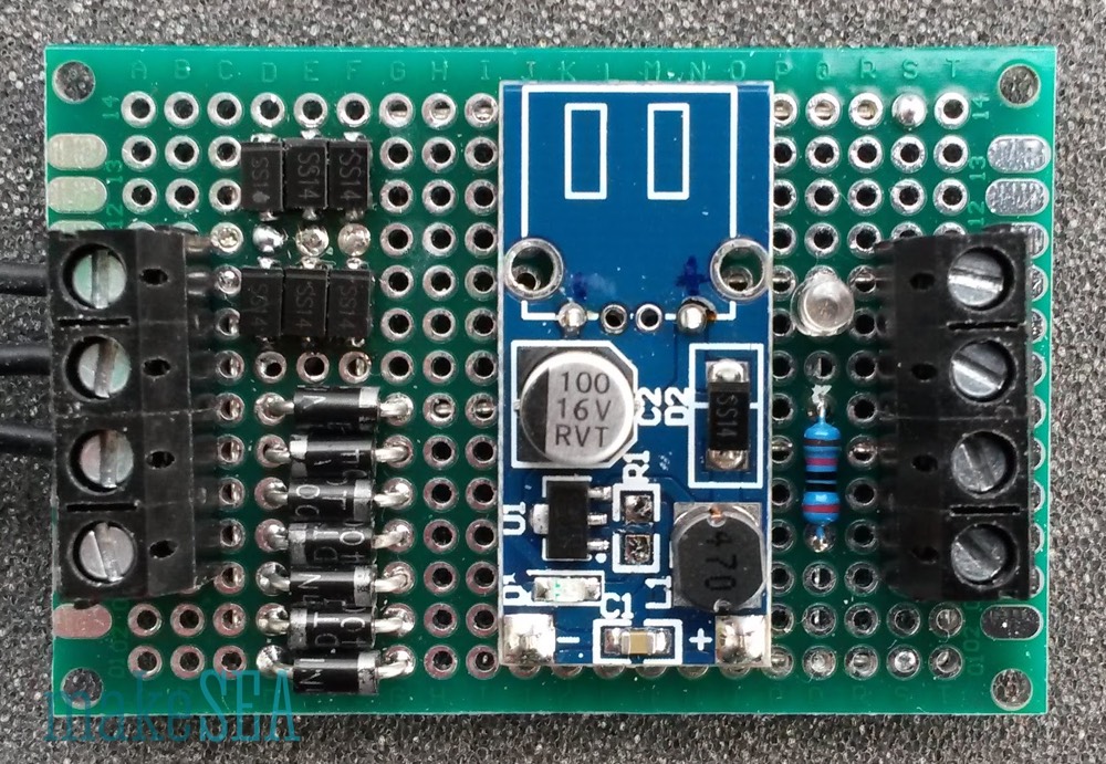
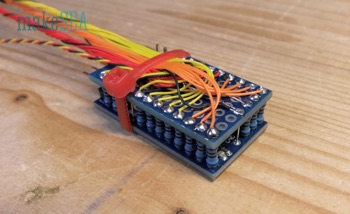
I’ve used the SMD-version of the Schottky diodes (SS14), because I had some spare parts. The SS14 is also available with a regular shape, easier to solder. I’ve also de-soldered the resistor R1 from the PFM module, because with only 1kOhm the LED on board consumers a relevant amount of current. I’ve also removed the USB-connector - it’s not needed, and I wanted to have access to the +5V output pad.
This charger works amazingly well. Without connecting the supercaps the output LED is already lit, when the generator is rotated only ¼ turn by fast manual move. It’s charging the supercaps below 200RPM, and the PFM module works already at 0.2V input voltage.
Theoretically a lithium battery could also be used instead of the supercaps. But the problem with the battery is the working range between 3.3V and 4.2V. The circuit would need to be changed: the battery needs to be charged by the PFM module.
Active Dump Load
The problem with the simplistic 7 diodes dump-load: the transition from no-load to dump-load is continuous (exponential). It would be better, if the dump-current was zero up until 5V (use all the energy to charge the supercap), and then it should have a steep increase and draw as much current as needed in order to pull down the voltage to 5V, if the generator voltage was higher.
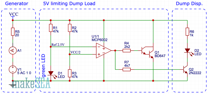
The circuit scheme has 3 main blocks:
- The generator-block is a placeholder of the actual generator and the rectifier helping to understand the functionality of the rest of the circuit. Important detail is the resistor as a placeholder of the resistance of the generator coils.
- The block with the 5V limiting dump load contains a green LED (D1), which is used as a voltage reference. It theoretically could be replaced with a 2.5V Zener diode (which I didn’t have available at the moment), but it wouldn’t improve the performance of the circuit anyway. The trick: when the voltage of the generator is increased linearly, the voltage at the positive input of the Op Amp also increases linearly. Differently the voltage at the inverting input of the Op Amp increases logarithmic, because of the diode. Exactly at the point where the two input curves intersect, the output of the opamp goes up from low to high, and the darlington-transistor (Q2) pulls down the supply-voltage. It stays stable at 5V. The darlington-transistor has a TO-220 case. With 200mA it burns 1W and gets slightly warm - with more current it needs a heatsink. Theoretically it could handle a current up to 8A (far more than the generator creates).
- The last block is only a display with an LED (D2) that lights up, if the circuit is dumping superfluous current. The LED and the transistor (Q2) actually operate as well as a little dump-load with the current limited by R6.
I’ve implemented the circuit above on a breadboard, and done the measurements using an adjustable power supply. The graph also includes measurements of the 7-diodes dump-load. The y-axis shows the total current drawn from the generator.
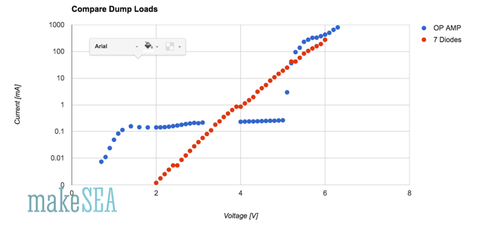
Below 5V the circuit with the circuit draws roughly a constant current of 0.25mA (2 x 0.05mA by the voltage divider and the voltage reference, 0.15mA by the Op Amp). At 5V there is a steep increase (depending on the resistance of the cables from my power supply). Below 3.5V the 7-diodes have a better performance: At 2V the Op Amp wastes 100 times more current than the diodes - current, which could be used to charge the supercap. However the absolute value of the current needs to be compared with the current needed finally by the microcontroller. An Arduino Pro Mini with some LEDs connected will need at minimum 5mA, so it’s not relevant if 0.25mA are lost.
As next the circuit would need to be properly soldered on a PCB, but I’ll wait until the rest of the wind turbine is finished (the circuit with the diodes as dump load is good enough for testing).
Testing the Generator and Charge Controller together
Finally! The generator and the Charger v1 with the passive Dump Load are connected (not yet the active Dump load). The generator is fixed on the drill-press (which has luckily a RPM-display). The rectified voltage is measured depending on the generator rotation speed. No capacitor or any other load is connected.
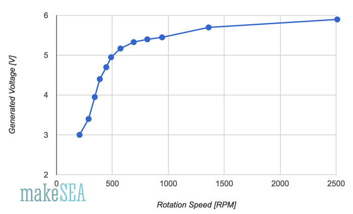
Up to 500 RPM the voltage increases approx. linearly until 5V. At higher speeds the voltage is almost flat. That’s the expected effect caused by the passive dump load (7 diodes). Up until 5V the dump-load is not dumping much current - the voltage can increase corresponding to Kv. At higher rotation speeds the diodes are “eating” more and more current. The superfluous energy is then wasted as heat in the diodes and the generator copper wires. If there was no dump-load attached with Kv=80 RPM/V the generated voltage at 2’500 RPM would be at 31V.
Interesting to note: at 200 RPM the generated voltage is around 3V.
The next measurement is the current with the rectified signal short-circuited:
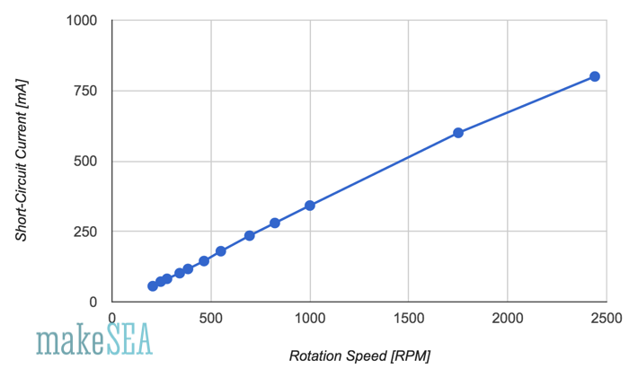
The curve is almost perfectly linear. As expected. The resistance of the generator copper wires is the reason. The induced voltage increases linearly with the rotation speed (U = RPM/Kv), and since the resistance is constant, also the current increases linearly (I = U/R). Assuming 31V at 2500RPM with 800mA current, the generator has a power loss of 25W - all heating up the copper wire. In-deed after only 30 seconds on the drill-press, the stator is remarkably warm.
Interesting to note: at 200 RPM the short-circuit current is over 50mA.
Power/Current Consumption Estimation
How will the system behave with an Arduino attached? Will it be possible to light 20 LEDs, and still charge the capacitor? Which wind speed is needed for “break-even”? How long will it run with fully charged capacitor and no wint? The answers will potentially influence the software requirements for the microcontroller.
Arduino Pro Mini 3.3V, 8MHz:
- 20mA running original
- 3mA at boot-up (resistor of red status LED de-soldered)
- 0.5mA running with simple sleep delay (resistor of red status LED desoldered)
- More hacks (power down sleep, 50uA): https://andreasrohner.at/posts/Electronics/How-to-modify-an-Arduino-Pro-Mini-clone-for-low-power-consumption/
⇒ 3mA needed at minimum
LEDs:
- Red LED needs 2V, green or blue needs 2.7V
- Connect with resistor to 3.3V, not possible to have 2 LEDs in series.
- LEDs need to be well selected
- I have a greed LED which appears quite bright with only 0.125mA, however will drive them with 1mA (not all LEDs will be ON at the same time)
⇒ Max. 21mA with all green LEDs turned on (7 LEDs per propeller blade, 3 blades)
Hall Switch (3141):
- Datasheet: supply voltage 4.5V .. 28V
- Datasheet: supply current 4.4mA .. 9mA ⇒ that’s a lot compared with the rest
⇒ connect to Arduino RAW (5V)
⇒ high power consumption, use additional transistor to turn it on or off
⇒ evaluate magnetic reed-switch?
- Test at 5.0V: draws 3.2mA .. 4.3mA
- Test at 3.3V: draws 2.8mA .. 3.6mA ⇒ :-) that’s my choice (even if it’s out of specs)
- Test at 2.7V: draws 1.8mA .. 2.0mA
- Test at 2.6V: Works “analog” no switching trigger point
- Test at 2.5V: Works “analog”
- Test at 2.4V: Fail
Conclusion
The whole system consumes 3.3mA .. 5.0mA if the LEDs are OFF. At maximum 26mA if all LEDs are ON. The generator produces 3V and 50mA at 200 RPM, which corresponds to 1.7m/s (6km/h) wind speed. Wind as fast as walking speed should be enough to charge the capacitor and drive the microcontroller together. Or even better: 1 hour of walking speed wind should theoretically produce enough energy for powering the microcontroller more than 10 hours. Let’s see …
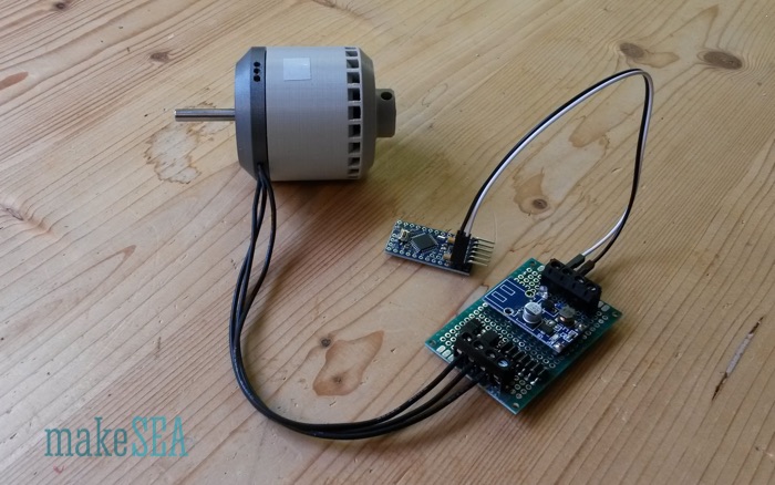
For demonstration I’ve connected all with an Arduino Pro Mini. In the video I’m turning the generator with my hand (very slowly). The green LED on the charge controller lights up, and the red LED on the Arduino is flashing randomly and bright while it’s booting. Once booting is finished, my program starts running. The program on the Arduino does a short double-flash with the red LED every two seconds. In-between the arduino is sleeping.
Components: Wind Turbine
Summary
This Wind Turbine is not just a Wind Turbine. Wind is driving a 3d-printed propeller and a 3d-printed generator. The generator charges a super-capacitor (or a battery), and produces electricity for an Arduino, which sits in the 3d-printed propeller hub. The Arduino switches on and off an array of LEDs located in the blades. If the propeller is spinning at a certain speed, the blinking LEDs will paint an image into the air. It can display various messages (e.g. wind-speed or the time).
Of course this display is difficult to read during the day with glaring sun-light, or if there is no wind. Anyway it’s a demonstration of the future - the Internet of Things is coming: there will be a web-server inside the propeller-hub, the energy stored in the battery will be used for communication. Users will be able to browse this Wind Turbine with their Smartphone. They will obtain weather information, and they will be able to post their tweets onto the propeller, even if there is no wind … ;-)
With this project I wanted to create something, which is crafted mainly by using the new element: 3d-printing filament! Components, which are not 3d-printable should be minimized, and they should be very basic: copper-wire, magnets, screws. Intelligence is inserted into this system by using an Arduino. All the project details are open-source, published on makeSEA.com. People with a 3d-printer, a solder iron, and an Arduino in their workshop should be able to “download” this Wind Turbine, or parts of it.
I’d like to sensibilize people, that the world of today has a heart, and humans are responsible for it. A smart-phone is not smart - the inventor of this phone is smart! We all are humans, and we should consider our potential. The Wind Turbine demonstrates the use of ecological energy. It’s an autonomously working gadget. Eco friendliness, luxury, and fun are partners. The reason how the Wind Turbine works is not just magic - it’s simple physics and not religion. If somebody walks through this project, he (or she) will have a different view at the “modern” gadgets. I’d like to encourage people to not just stack huge and complex building blocks on top of an unknown base. It could be very dangerous, the system behaves unpredictably and operates very inefficient. Look behind the scenes and have fun!
System
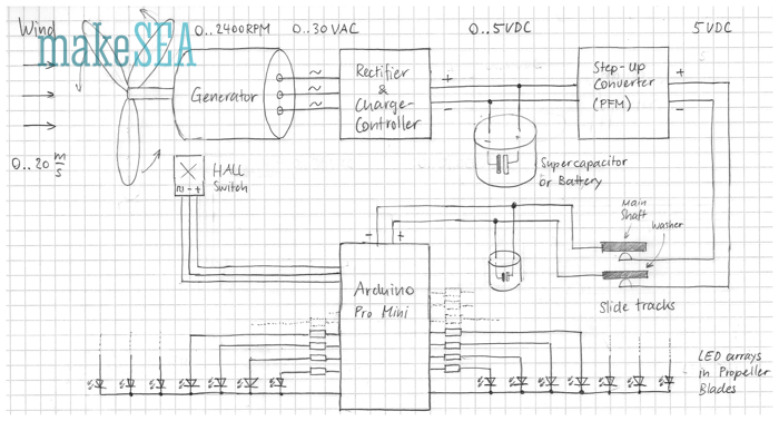
The wind turns the propeller and the direct driven generator. The generator produces 3-phase AC voltage. The AC is then rectified, and limited to 5V. The overvoltage is “burned” (dump-load) in order to prevent overloading the super capacitors. A step-up converter creates constant 5V even if capacitors are not yet fully charged. In the propeller hub there is an Arduino, which controls 7 LEDs in each blade. A Hall-Sensor triggers a signal with each full revolution, and the Arduino uses this signal in order to turn on or off LEDs, and “paint” a stable pattern with the LEDs.
Rectifier, Charge-Controller and Step-Up-Converter are all on a single PCB. For simplicity I’ll often name this PCB only Charge-Controller.
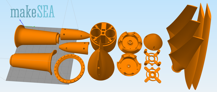
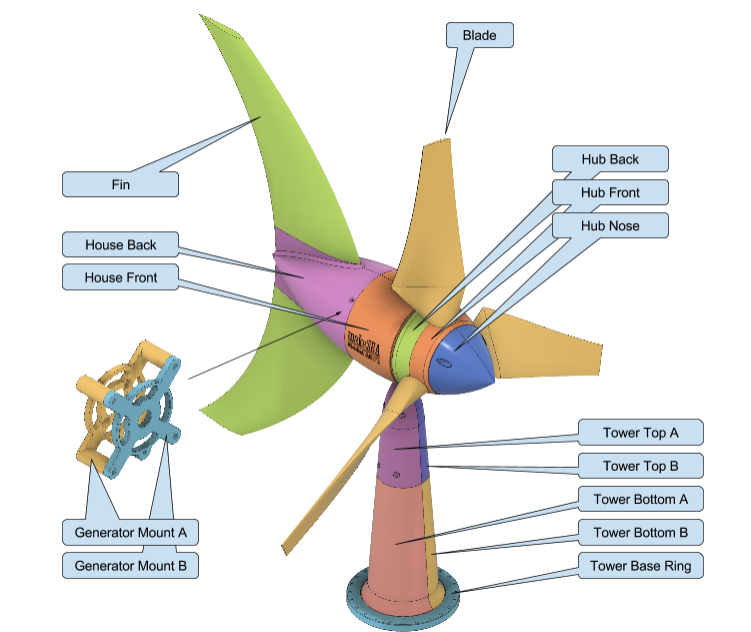
Main Components
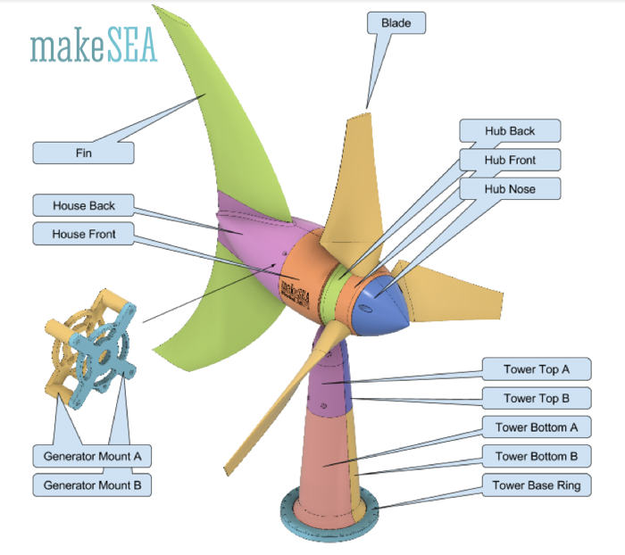
These are the main 3d-printable (exterior) components for the Wind Turbine. They are held together with 17 screws. Most parts can be printed without support. Support is needed for the tower parts, house front, hub back. Printing orientation: largest flat surface oriented towards print-bed.
Internal Components
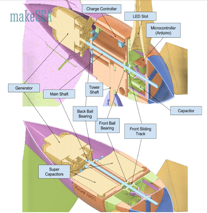
Descriptions about the generator and the charge controller can be found in the other documents about the development of these internal components (“Wind Turbine internal Components”). Maybe I’ll merge these files later ...
If one long shaft is used connecting generator and propeller hub directly, the back ball bearing in the house and the front ball bearing in the generator are not needed.
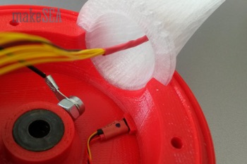
Sliding Tracks:
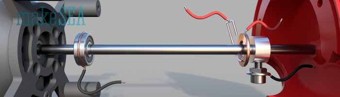
Sliding tracks minus pole: (ab-) using a ball bearing (next to generator):
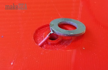
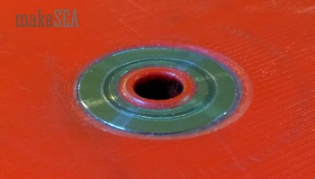
Sliding tracks plus pole:

Gluing a 8x16mm washer with epoxy4:
4. The washer needs to be level or flush with the housing so that when the turbine turns it will not “wiggle” -D.Hartley
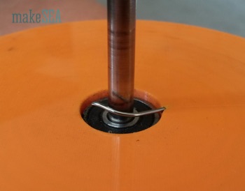
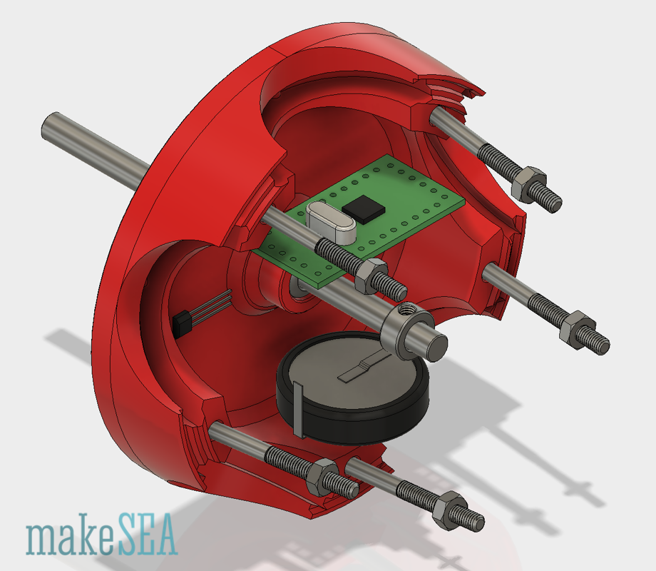
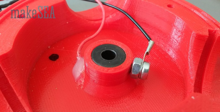
Connections inside the propeller hub. Plus-pole from washer, minus-pole from shaft collar:
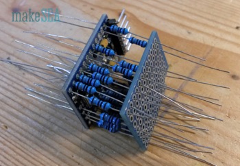
LED arrays:
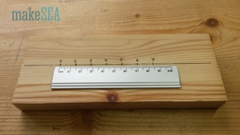
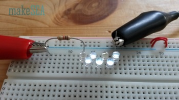
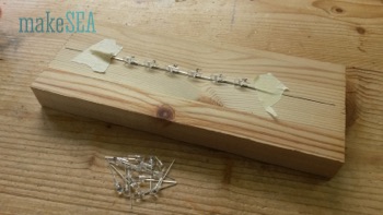
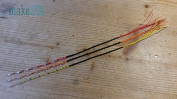
Seven 3mm LEDs with 14mm spacing. Before soldering the LEDs, check if they actually all work: connect 7 white LEDs in series with 1kOhm at 18V, and they should all evenly bright light up.5
5. If you do not have a good wire stripper to strip thin wires, then I would recommend using a lighter to light the end of the wire and just pull the plastic off. It works great, but be careful! To avoid problems, I would recommend soldering each negative lead of the LED together with 14 mm of spacing for each blade (3 sets of 7 LEDs). Then I would start from the top of the LEDs and solder the thin wire to the positive lead of the LED and weave the wire around the rest of the LEDs (shown above). The wire needs to extend from the last LED at least the length of the LEDs soldered together, but it can be longer, you just might have to cut it later. Once all seven of one strand of LEDs are soldered with wires then shrink tube at least half the length of the wire extending from the last LED. This will make it easier to manage the wires in the housing. Do this again for the other two strands of LEDs. Once all of the LEDs are wired and shrink tubed, then you are good to move on. -D. Hartley
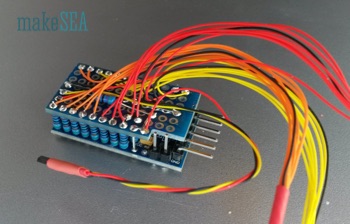
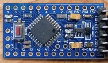
Arduino: We are using the 8MhZ, 3.3V version:
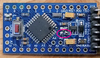
De-solder the 1k resistor from the red power-indicator LED. It’s useless: needs 80% of the energy, in case the Arduino is set to sleep (if there is no wind).
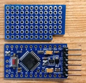
Using a PCB with 7 x 12 pads. Connecting EACH analog and digital pin with a resistor (180Ohm with white LEDs).6
When using A6 as input for the Hall-Switch, a pull-up resistor 4k7 is needed.7
6. For this step, you will need 22 180 Ohm resistors. You will also need to connect the PCB to ground terminals on the Arduino using leftover parts from cutting the resistors. In total, 3 ground terminals will be wired to the PCB, and 22 Resistors will be connected to terminals TX0, Rx1, 2-13, and A0-A7. 20 of these terminals will be wired to LEDs. The ones that are not wired to LEDs are A6 and A7. A6 is wired to the Hall-Switch, and A7 is not wired to anything. -D. Hartley
7. The 4k7 resistor is soldered to VCC and A6. -D. Hartley
Arduino Pro Mini has only 20 outputs. With 7 LEDs and 3 propeller blades, 1 output is missing. I’m “cheating”: leave one of the inner LEDs unconnected. Use pins 0-6 for Blade A, pins 7-13 for Blade B, A0-A5 for Blade C (1 inner LED unconnected), and A6 or A78 for the Hall Switch. Basically all LEDs could be wired randomly - make soldering work simple. The final connection scheme can easily be adjusted in the software.9 Instead of the Hall Switch, a Read-Switch maybe also works.
8. A6 (only) for the Hall Switch.
9. I would not recommend doing it this way as it will take time to go through each wiring of the LED and line it up with the code. Also using different colored wires helps a ton. -D. Hartley
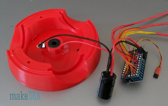
Magnet and Hall-Switch:
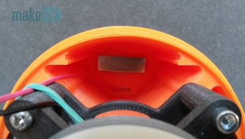
The magnet in this image is glued into the front house with hot glue, the published design has a proper spacing, where a 3 x 10 x 30 mm magnet can be snapped in. There is also a proper space in the back propeller hub for the Hall-Switch. Carefully test the system before firmly gluing all components: the Hall-Switch works only with one orientation of the magnetic field (maybe you need to flip the magnet or the switch).
More on the Installation of the Capacitors and How they Work:
A capacitor (or also a battery) can be compared with a reservoir. The water pressure corresponds to the voltage. Water flow (gallons/sec) corresponds to the current. A water pump makes the water flowing through the pipes - pressure at the output is higher that at the input.
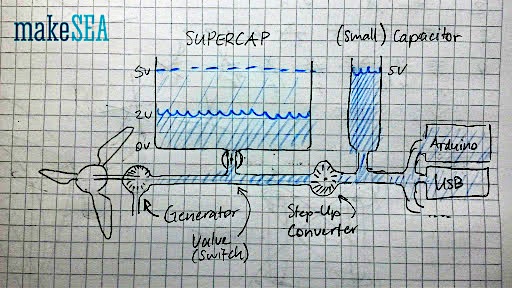
The windpowerWriter has a big reservoir (supercaps) and a small reservoir (little capacitor in the hub). The voltage from the generator (1.pump) depends on the wind speed. The step-up-converter (2.pump) generates always 5V as long as its input voltage is higher than 1V. In my demo-turbine I've added this switch at the bottom of the house (valve), which allows to disconnect the supercaps. If the supercaps are connected (valve open), the generator charges the supercaps AND supplies the step-up-converter together. If the supercaps are disconnected (valve closed), the generator only supplies the step-up-converter, and the charging state of the supercaps remains constant. Usually supercaps are connected (valve open). I.e. the step-up-converter can output 5V even if there is no wind - it discharges the supercaps.
For the life-demo I've added the switch, because the arduino would always run, and people couldn't recognize, that the generator is actually working when there is wind. And if the supercaps are completely empty it takes a wile, until they are charged at the minimum level required for the step-up-converter.
You should connect the caps at the input of the step-up-converter (like illustrated in the google-drawing below). The washer is connected at the output, and the Arduino would only work in a very small range, if the caps are fully charged (4.5V to 5.0V). Interrupting the plus-wire is OK. Make sure, the capacitors are in series, and with proper polarity. Charging 500F-Capacitors takes some time. I had the fan blowing at the turbine for roughly 30 minutes, until the capacitors were charged to approximately 1V. Below that voltage, the step-up-converter wont work (and the Arduino isn't powered). The behaviour of charging capacitors is similar like filling a pool with water: with a constant current, the voltage increases continuously.
Software
- Text (or image) is rendered into a global pixmap with polar coordinate axis. 7 pixels as radius, and a specified number of pixels as angle (depends on the rotation speed and power of the micro-controller). One byte is used for the radial dimension (each bit for one LED - 1 bit is unused).
- Measure the time per revolution. Depending on the current time, the current angle of the propeller blade(s) can be calculated.
- The blade-angle is used to calculate the pixel-index, and LEDs are switched on or off depending on the pixmap content.
- The global pixmap is changed occasionally with alternating text, patterns, or actual measurements.
Frequently Asked Questions (FAQ)
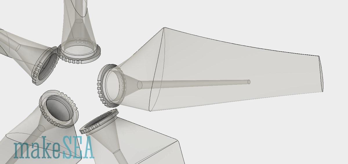
What is the preferred position to print the blades?
The blades for this project can be printed standing up, assuming you have good plate adheasion. At 100%, this requires a printer with a footprint at least as tall as 10 inches or, 250mm. Supports should work but also are not necessary.
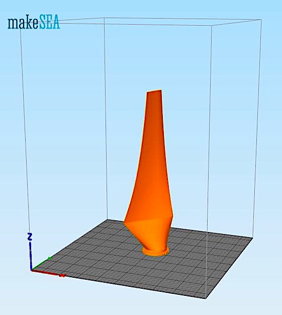
We used an Ultimaker2 Extended at .15mm layer height and 30% infill, using translucent PLA filament. The Pro Series PLA avaialable from MatterHackers comes out georgous! On a shorter printer, you may need ot modify the original blade to be shorter with the supplied master file, or to print in interlocking pieces. You can also print on its side with support. Our other Propeller project does print on it's side, along the trailing edge with support, and works great. Don't forget to register your alterations with makesea and link back to the original design!
How do you fit the drive shaft on the rotor?
The drive shaft is supported by bearings that are nested in the sheild and hub.
Can the blade angle be adjusted. Did you test the influence of their angle at given wind speeds?
The blades in the current design are slightly oval at the base and prefer a fixed, optimized position based on arodynamics to produce the least drag possible at low wind speed. The Arduino code is programmed accordingly. The blades can be adjusted but there will be a slight gap between the front and rear of the hub. This can be modified using the supplied source files. Larger blades, or high-wind conditions may benefit from some adjustment for optimal performance.
Sign In to Download
This collection of useful parts and objects is yours to use. All we ask is that you register derivative projects with makeSEA to help track their evolution (privately or publically).
You can also use makeSEA to share or sell your designs and mashup your work with the work of others. Keep track, and ensure that everyone that contributes receives attribution.
Protected files are makeSEA assets that can be distributed to other systems and link back to the original files at makeSEA. You can distribute these reference assets freely without concern for access restrictions. makeSEA still requires users to login to access the unprotected original files.
Share! Print! Go make something!
Please Sign In to access the complete collection of unprotected files in makeSEA.
Parts List
The following list consists of the non-printable items needed to complete the assembly of the windpowerWriter:
- 4 + 4 + 3 Nuts M3
- 4 Bolt Screws M3, 35mm, Socket Head (generator mount, no nut - directly into plastic)
- 4 Bolt Screws M3, 10mm, Flat Head (generator mount)
- 3 Bolt Screws M3, 42mm, Socket Head (hub)
- 4 Bolt Screws M3, 25mm, Socket Head (tower top)
- 2 Bolt Screws M3, 25mm, Socket Head (tail fins, no nut - directly into plastic)
- 4 Tapping Screws, 3mm x 8mm, Flat Head (house back, directly into plastic)
- Washer 8 x 16 x 1 mm (sliding track)
- 0.6mm spring wire for sliding contact
- 5mm Shaft, 230mm long
- 2 Ball Bearings 5mm x 16mm x 5mm (shaft house),
- Shaft collar 5mm, 13mm outer diameter, 7mm long, with M4 socket screw
- M8 Bolt, 160mm, no Head (tower jaw shaft)
- 4 Nuts M8, 6.5mm thick (tower and house)
- 2 Ball Bearings 8mm, 22mm outer diameter, 7mm thick (tower)
- 1 magnet: 3 x 10 x 30mm, house front, for HALL switch
- Enameled Copper Wire, 0.21mm, 3x15g (or 3x40m), for Generator
- (magnets, ball bearings, collar, etc … see “brushless motor”)
- Arduino Pro Mini
- 22 180 Ohm Resistors (other resistor values can used, but will yield a different brightness on the LEDs)
- 1 4k7 Resistor
- 1 PCB Board
- 1 Hall Switch
- Spool of skinny wire
Additions to above referenced list made by D. Hartley.