
makeSEA 3D Printed Brushless Motor v2
by Christoph Laimer
Brushless Motor Model A001
(see also, windpowerWriter)
(see also, Selecting the Magnets)
(see also, Brushless Motor v0, prototype)
Introduction / Summary
There is 3D-printable magnetic PLA from Proto-Pasta. Some applications are published, where the material was used because of its special surface look-and-feel: e.g. make objects with a rusty patina. Is there an application, where its magnetic properties can be used? Actually it should say “ferromagnetic”, because the material is not a magnet, and it also can’t be permanently magnetized, but it’s attracted by a magnet.
With its properties the material could be very useful to 3d-print special shaped cores for electromagnetic coils. E.g. a brushless motor. First tests with the magnetic behavior of this material show, that the magnetic PLA is much less magnetic than common things made of steel. On the positive side the material is not conductive: therefore there is no danger to create short-cuts when winding the coils, and there are no eddy currents.
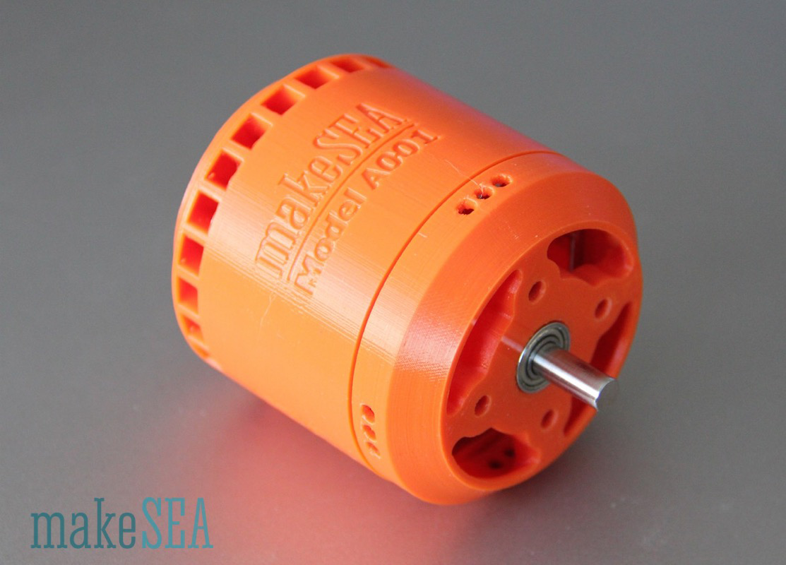
The resulting design is a brushless motor, which can be controlled by a common ESC from RC-toys. It’s powerful enough to drive a car (efficiency is higher than 60%). The motor can be 3d-printed with a common printer (Ultimaker, Makerbot). Non-printable parts are easy to source at ebay or other online-stores. Measurements show, that these is even more potential that could increase power and efficiency.
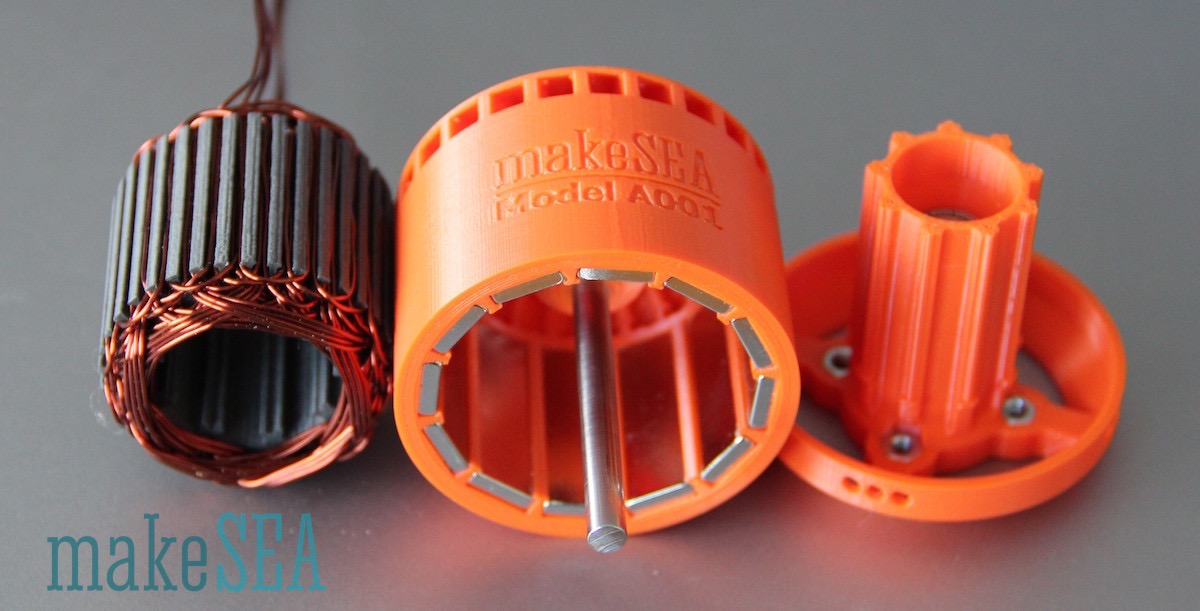
Components
The motor consists of 4 main parts, which are 3d-printed:
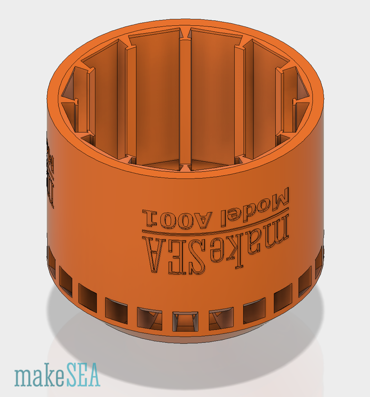
| BL_StatorShield.stl
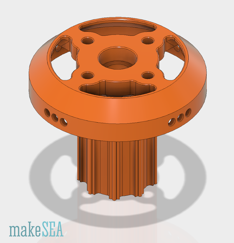
Stator Shield: Screws, Ball-Bearings, PETG or ABS (no PLA - there are potentially big vibrating forces) | BL_StatorWindingCore.stl
|
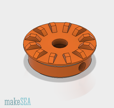
| BL_Rotor.stl
Rotor: Magnets, PETG or ABS (ferromagnetic material would be great, if it could sustain high centrifugal forces). Magnetic PLA is not recommended as it’s very brittle. | BL_RotorCollar.stl
Shaft Collar, connecting the Rotor with the shaft. Recommended material is PETG or ABS. |

Further needed non-printable pieces:
- 1 Shaft: Diameter 5 mm, Length 90 mm, ideally hardened Steel
-
2 Ball Bearings: Inner Diameter 5 mm, Outer Diameter 10 mm, Width 4 mm
-
1 Shaft Collar: Inner Diameter 5 mm. Outer Diameter 9 mm, Width 5 mm, long set screw
-
4 Nuts and Bolts, M3, Nuts 2.5 mm thick, 5.5 mm smaller Diameter
-
12 Magnets, Length 30 mm, Width 10 mm, Thickness 2.8 mm (Chinese supplier specified 3 mm)
-
12 m Enameled Copper Wire, Diameter 0.67 mm (approx. 50 g)
-
Connectors, cables, heat shrink tube, etc. (depending on the final application)
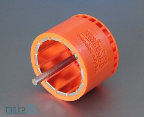
Winding Tool:
|
The tool helps while winding the wires. Wires can be taped to the handle, or excess wires can be pushed into the handle. | BL_WindingToolHandle.stl BL_WindingToolHolder.stl BL_WindingToolScrew.stl
Critical part is the screw: it has 1.5 mm pitch, 60° overhangs. Prints very nicely on UM2 with PETG. |
Fabrication (printing, assembly)
The motor pieces are not very difficult to print, however they need to be as accurate as possible. Use high resolution settings, print at slow speeds. Centrifugal forces are high and unbalanced parts can cause big vibrations, noise, or maybe the motor can be destroyed.
Rotor:
Needs to be well balanced. The hole for the shaft in the 3d-model is exactly 5 mm, and when printing, it will usually be a bit smaller due to printing inaccuracies. That’s desired, because the shaft needs an accurate tight fit in the rotor. Use a drill press to adjust the bore exactly to the shaft. Don’t drill at high speed, as this would cause the 3d-printed material to melt. Also drill out the hole of the 3d-printed shaft collar, insert the metal collar into it, and use a long grub-screw, in order to fix both (metal, and 3d-printed) collars to the shaft.
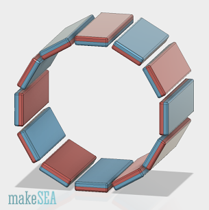
Insert the magnets with alternating polarity into the slots of the rotor. In order to well balance the rotor, it’s recommended to weight the magnets before assembling, and position magnets with similar weight at the opposite slots. E.g. if magnets are sorted by their weight, they could be inserted in this sequence: 1, 4, 5, 8, 9, 12, 2, 3, 6, 7, 10, 11.
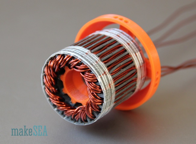
Stator:
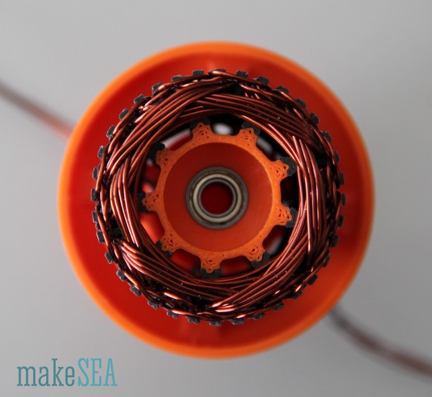
Insert the nuts into their space. Nuts and front ball bearing are very close together, and they should be able to sustain a bigger load (because the plastic stator isn’t as stiff as if it was made of metal, it’s recommended to connect the pulley / propeller near to the front bearing). The stator winding core slides simply onto the designated rails. There are big gaps to allow sufficient air-flow. Plastic will not sustain high temperatures, and since inferior efficiency is expected (compared with a common brushless motor), it’s very important to carry aways all the heat. Push the ball bearings into their designated space. The winding core is held in place by the rail-friction and the cables (or a bit of glue if needed). Before finally attaching the winding core, the wires need to be wound.
Winding the Stator
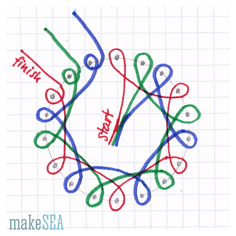
The stator has 36 slots. In each slot there finally need to be 6 wires (the illustration below shows only 4 wires and only phase A for simplicity reasons).
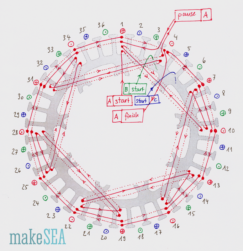
The basic scheme is very simple. There are three coils resp. Phases (A red, B green, C blue). In each slot the current of all the 6 wires needs to flow into the same direction (current in opposing directions neutralizes its effect and is not desired). Continuous lines in the illustration are wires in the foreground, dotted lines are wires in the background. The big dots indicate wires in the slots, from front to back (or reverse). The “plus” in the circle indicates the direction from front to back, the “dot” in the circle indicates the opposite direction.
While the basic scheme is simple, the actual winding is a bit more complex. The main problem for winding an electrical motor isn’t the small space for wires in the slots, but all the overlapping and crossing wires going from one slot to another slot. Wires are passing in front of other slots and therefore block the entry for other wires … In order to resolve this, the winding is mixed in lower and upper layer turns. I.e. There are 4 lower layer turns (only 2 are illustrated), and 2 upper layer turns (as illustrated).
-
Start wiring with the red wire in slot #1. Keep 15 cm extra wire, slide it through a hole in the winding handle, and fix it with tape. For all 6 lower layer coils, make 4 turns (only 2 illustrated in the picture).
-
When all the big 6 lower layer coils are completed with four turns at slot #4, make a “pause”: i.e. cut the cable with 1.5 m excess wire, fold it, and push it into the handle.
-
Do the same with the green wire starting at slot #3. The pattern is exactly the same as for the red wire just 3 slots shifted. Also pause after the lower layer coils at slot #6.
-
Do the same with the blue wire starting at slot #5, and pause st slot #8
-
Continue with the red wire (remove it from the winding handle), do 2 upper layers: continue to slot #1 go back leave 2 slots empty, go front, leave 2 slots empty, go back, etc.
-
Do the same for green and blue wires.
In principle it’s possible to change the scheme as long as the current flow direction and phase per slot matches with the illustration (e.g. only the upper layer scheme with 6 turns).
Once all the wires are in the correct slots, the wires probably need to be well aligned, and they should not sick out of the stator (the moving rotor will touch and damage badly placed wires). In order to push and bend the copper wires, never use metal. Better use wood, or plastic (you can 3d-print a “credit-card”).
Finally trim all the 6 wire ends to the same length and remove 5 mm of it’s isolation. Later all the 3 “start” wires can be connected and soldered together (Wye- resp. Star-Connection). The image below illustrates the Wye-connection (not the actual winding):
Maybe you want to experiment with Delta-connection (triangle). For more information see https://en.wikipedia.org/wiki/Brushless_DC_electric_motor#Variations_in_construction
When sliding the winding core onto the Stator-Shield, the wires can be either guided through the vent-holes (for testing) or through the small holes the the side (final wiring).
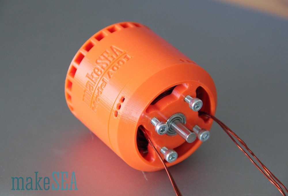
Basically the motor is now finished. The rotor firmly connected with its shaft can be pushed into the ball-bearings. The magnets pull it over the stator. In order to prevent the stator from moving out of the bearings, the pulley (or propeller) needs to be mounted on the front shield.
Tests and Measurements
Now it’s time for the truth. It will turn, but how well will it perform?
Before connecting a motor to a power source, it’s best to check with a multimeter, if there are no short-circuits between the wires. The 3 wires need to have all the same resistance.
| Wire Length per Phase (approx.) | 3500 | mm |
| Wire Diameter | 0.67 | mm |
| Resistivity Copper | 0.017 | Ohm*mm^2/m |
| Resistance per Phase (calculated) | 0.17 | Ohm |
| Resistance per Phase (measured) | 0.19 | Ohm |
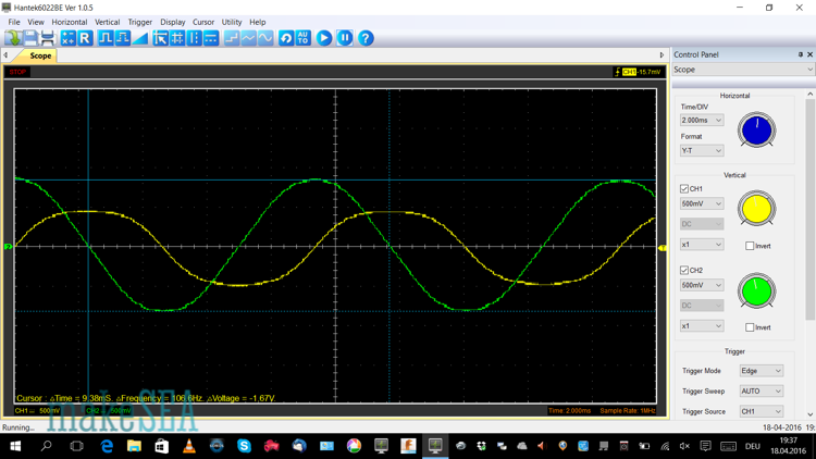
That was the simple test - next is the estimation of the expected rotations per minute (RPM). If the motor rotates too fast, things can get really dangerous. The centrifugal forces can get really high, and the rotor maybe “explodes”. Magnets become dangerous projectiles and potentially cause serious injuries. Therefore: Never stay in the plane of rotation! Remain either in front or behind it! But for safety reasons we’re going to test the motor first as generator: fix the shaft at electric drill, and connect the two ends of the red wire A to a scope (or a multimeter).
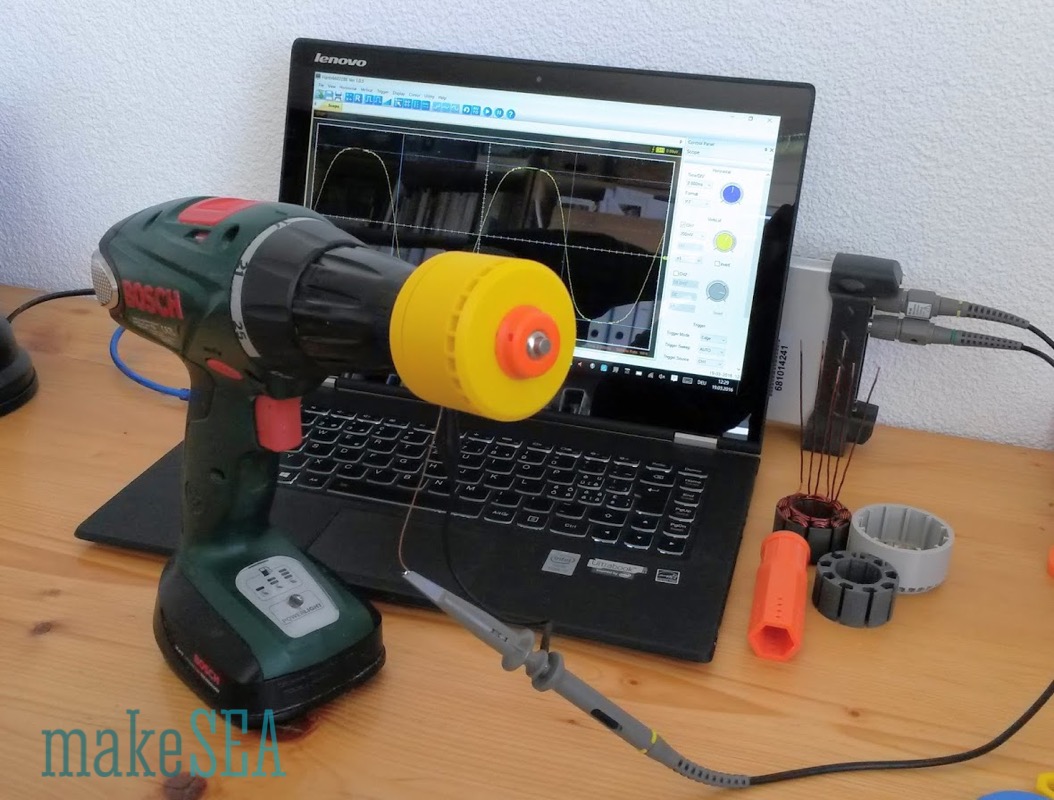
On the scope it’s simple and accurate to measure amplitude voltage and frequency (can be transformed to RPM). With a simple multimeter you would need to measure AC-voltage, and the RPM from the drilling machine specifications.
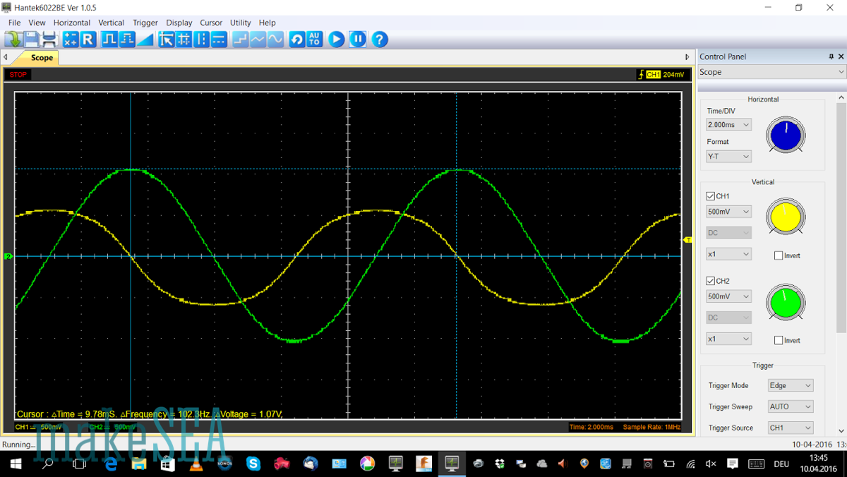
The yellow curve is the generated voltage from a single phase (e.g. the red wire). The green curve is the generated voltage from the two other wires (blue and green) connected in series, similar to the star-connection scheme. The measured frequency is 102 Hz - with 12 magnets of alternating polarity the frequency needs to be divided by 6 in order to get the generator revolution speed.
| Rotation Speed | 1’023 | RPM |
| Amplitude Delta-Connection | 0.595 | V |
| Amplitude Star-Connection | 1.07 | V |
| Kv (Star-Connection) | 1’006 | RPM / V |
Running this motor with 6 Cells NiMH (nominal 7.2 V) will result in 7’000 to 8’000 RPM - which is slow enough to not explode (there is a “funny” video on YouTube, where a 3d-printed rotor explodes at 36’000 RPM). This test also passed, and the motor was connected with the ESC from a RC-car. Without load the motor spins well, draws approximately 0.5 A from the battery. And it obviously has power reserves.
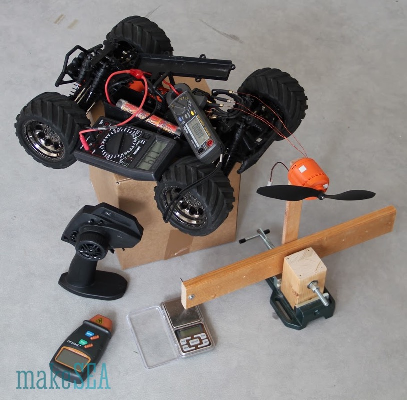
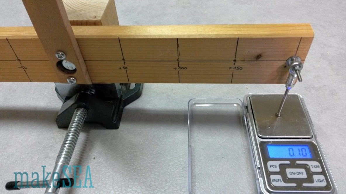
The ultimate test requires a more complex setup: need to measure efficiency with some load attached. As load a regular propeller was attached (10 inch diameter, 4.5 in pitch) - beating the air is a simple way to waste the motor shaft power. The simplest way to measure input power is right at the battery: voltage and current. The final output shaft power can be measured by multiplying rotation speed and torque (times PI). RPM is measured with a laser beam and a reflecting tag fixed at the rotor (can be ordered for a few $ at ebay). Torque is more challenge, but with some physics, math, and a construction with a 20cm long lever and a scale measuring at a resolution of 0.1 g it can be calculated.
Here are the numbers:
| (measured) | |||
| Battery Current (A) | Battery Voltage (V) | Motor Speed (RPM) | Motor Force (g) |
| 0.01 | 7.83 | 0 | 0.02 |
| 0.45 | 7.66 | 1'880 | 3.1 |
| 0.71 | 7.65 | 2'260 | 4.4 |
| 1.3 | 7.6 | 2'970 | 7.1 |
| 1.95 | 7.56 | 3'440 | 9.6 |
| 2.95 | 7.52 | 4'020 | 13.8 |
| 3.6 | 7.45 | 4'430 | 16 |
| 4.3 | 7.39 | 4'720 | 18.5 |
| 5 | 7.35 | 4'990 | 20.3 |
| 5.65 | 7.4 | 5'250 | 24 |
| (calculated) | (result) | ||
| Motor Torque (Nm) | Battery Power (W) | Motor Shaft Power (W) | Efficiency |
| 0.000 | 0.08 | 0.00 | 0.00% |
| 0.006 | 3.45 | 1.20 | 34.74% |
| 0.009 | 5.43 | 2.04 | 37.62% |
| 0.014 | 9.88 | 4.33 | 43.85% |
| 0.019 | 14.74 | 6.79 | 46.03% |
| 0.027 | 22.18 | 11.40 | 51.38% |
| 0.031 | 26.82 | 14.56 | 54.30% |
| 0.036 | 31.78 | 17.94 | 56.46% |
| 0.040 | 36.75 | 20.81 | 56.63% |
| 0.047 | 41.81 | 25.89 | 61.92% |
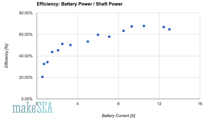
And here is the plot:
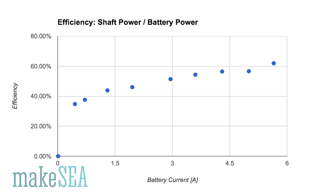
With 5 A Battery current and roughly 35 W power consumption, the overall system efficiency is at 60%. That’s not too bad - the losses also includes losses from the ESC and all the cables! The efficiency of the motor itself is therefore bigger than 60%. The values seem plausible - running the motor for several minutes at full throttle (5.6 A) does not dramatically heat up the motor. Final temperature is 30°C (with 20°C room temperature).
Also the measured torque makes sense:
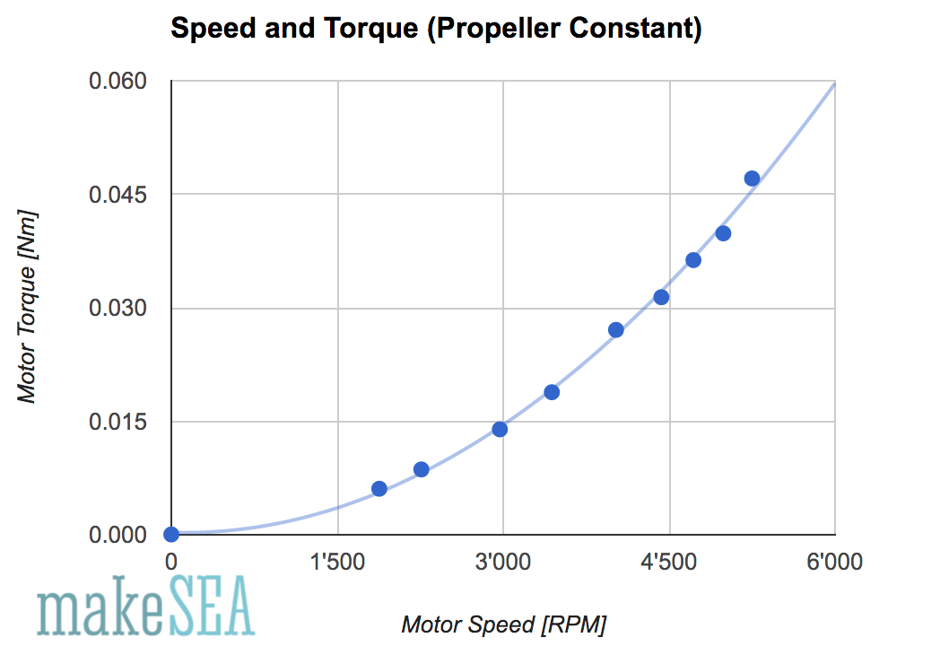
Torque increases almost perfectly with the square of the speed. This is a common behavior in aerodynamics.
Conclusions
Since the measurement methods are done with very simplistic manual methods, the measurement accuracy couldn’t be properly checked. Maybe the mistake could be bigger than 10%. It would make sense to repeat this with more professional instruments.
It would be interesting to measure the effect of the magnetic PLA. How much worse is the efficiency if the stator was printed with normal PLA? Can the efficiency be increased by using magnetic PLA for the rotor?
The motor definitively produces power enough to move a RC-car. Is it also enough for a small RC-plane?
The motor can digest more current (assumingly 7A - 10A) before it has a temperature problem. Which is the maximum power (watts) that the motor can produce? What happens with double voltage and higher RPM using a smaller propeller as a load (with the same propeller the current would quadruple > 20 A)?
Number of slots, number of poles and winding pattern is a science. There is almost an endless number of combinations. For this motor a “simple” scheme was selected, where wires can be placed close to the magnets (compensate the inferior material properties for the magnetic flow). The design is an heuristic approach, and certainly not the optimum. What’s the theoretic optimum using magnetic PLA from Proto Pasta?
Datasheet
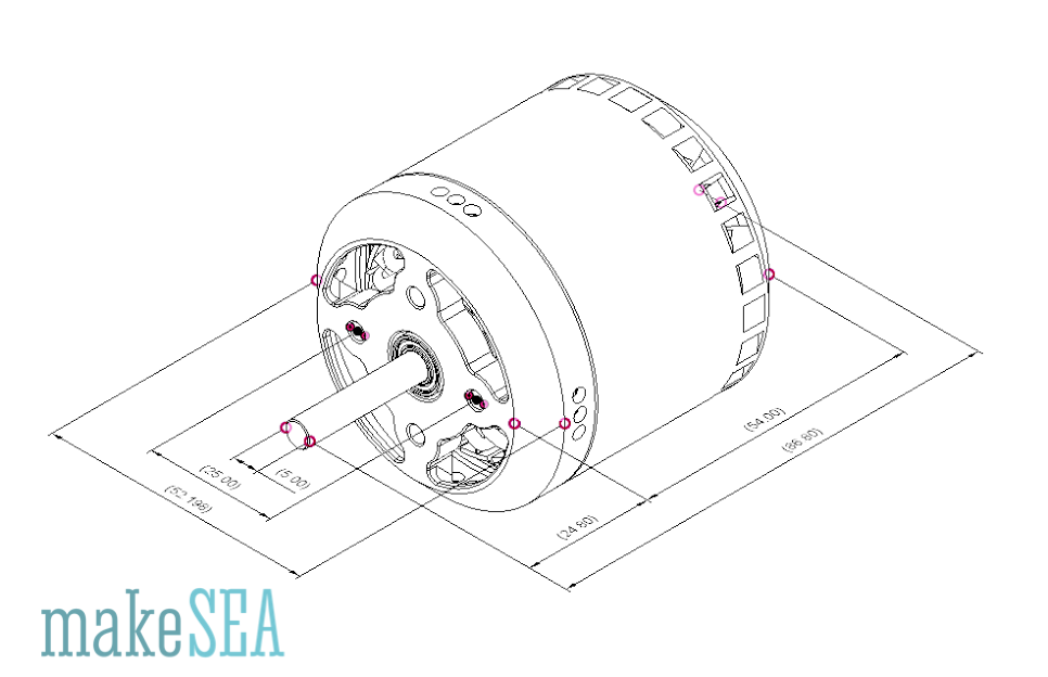
| Diameter | 52.2 | mm | Continuous Power | 42 | W | |
| Length | 54.0 | mm | Nominal Voltage | 7.4 | V | |
| Overall Length (incl. Shaft) | 86.8 | mm | Nominal Current | 5.6 | A | |
| Shaft Diameter | 5.0 | mm | Nominal Efficiency | 62 | % | |
| Screw Hole Distance | 25.0 | mm | Nominal Speed | 5’250 | RPM | |
| Screw Thread Size | M3 | Nominal Torque | 0.047 | Nm | ||
| Weight | 220 | g | Stator Height | 30 | mm | |
| Resistance per Coil | 0.19 | Ohm | Stator Diameter (air gap) | 40 | mm | |
| Poles | 12 | |||||
| Slots | 36 | |||||
| Turns | 3 | |||||
| Wire Diameter | 0.76 | mm | ||||
| Kv | 1’006 | RPM / V |
Links
https://en.wikipedia.org/wiki/Brushless_DC_electric_motor
https://www.youtube.com/watch?v=bCEiOnuODac
http://www.bavaria-direct.co.za/
Videos
/documents/12185/40127/20160410_201057.mp4
/documents/12185/40127/20160411_110702.mp4
3D Printed Brushless Motor v2
Brushless Motor Model A001.1
Introduction
The first real working 3d-printed motor “makeSEA Model A001” is a good starting point for the next level. The measured graph with its efficiency indicated, that it must be possible to get more power out of this design. In fact changes of the stator and the copper wire made it possible to create a brushless motor with almost 65% efficiency at 90W. The rotor remains unchanged - the same as “Model A001”.
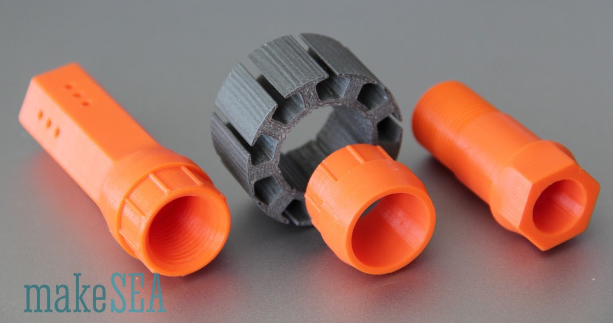
Components and 3d-Printing
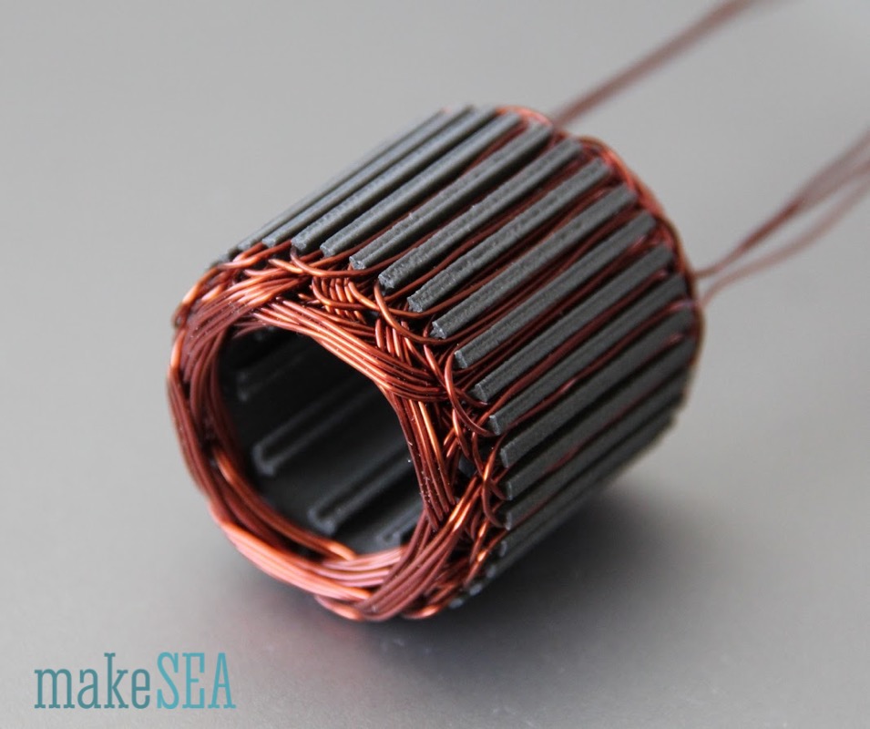
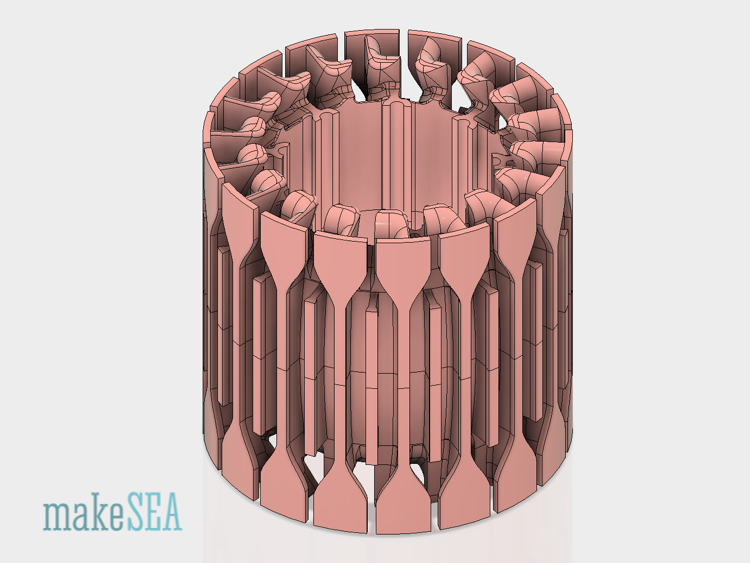
The components are all the same like the basic Model A001 except the stator. The stator is divided into two mirror symmetric parts. The division allows to 3d-print it without the need of support-material. The two parts are held together with the copper wire.
BL_StatorWindingCoreA.stl
BL_StatorWindingCoreB.stl
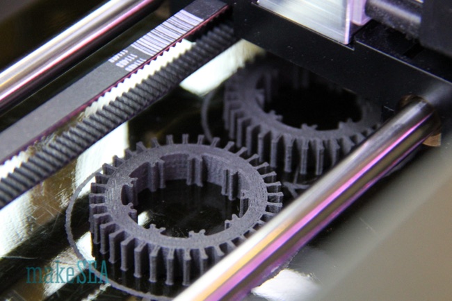
3d-printing with magnetic PLA from Proto Pasta works straight forward. Extrusion temperature is 200°C. The two halves can be printed at the same time.
As the Stator external dimensions didn’t change, all other parts from “Model A001” can be re-used: BL_StatorShield.stl, BL_Rotor.stl, BL_RotorCollar.stl. The same shaft, ball-bearings, shaft-collar, nuts, and magnets can be used. Only difference is the copper wire:
- Enameled copper wire: 1 mm diameter, approx. 10 m length (weight 60 g)
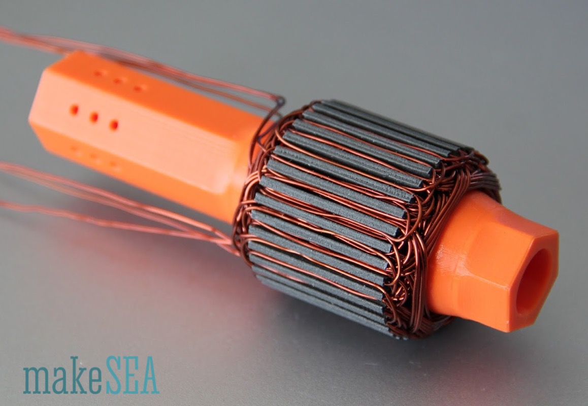
Stator Design and Winding
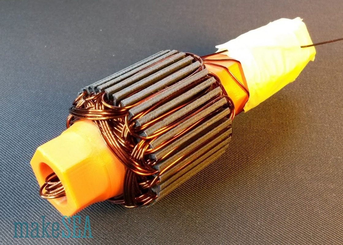
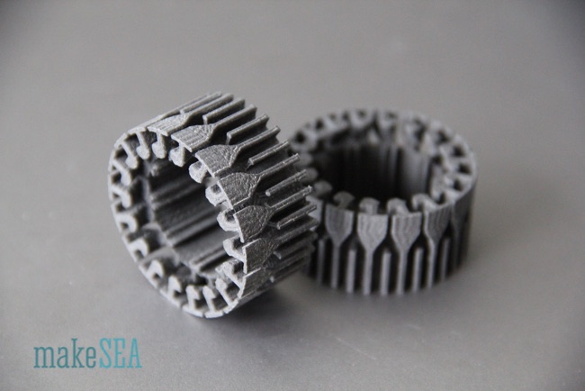
The stator winding core is completely redesigned. Only the number of slots (teeth) is unchanged. The length if the teeth is shorter. The head of every second tooth has a special shape, which helps to guide the overcrossing wires, hold them firmly in the slots. Thus winding is simpler, and no extra winding tools are needed - however the thicker wire diameter feels stubborn, and requires much more force. It can happen that the tooth-head breaks (magnetic PLA is very brittle). The heads are not relevant for the motor functionality, and just in case the wires can also be fixed with some strong tape (e.g. glassfiber reinforced tape - the author’s solution).
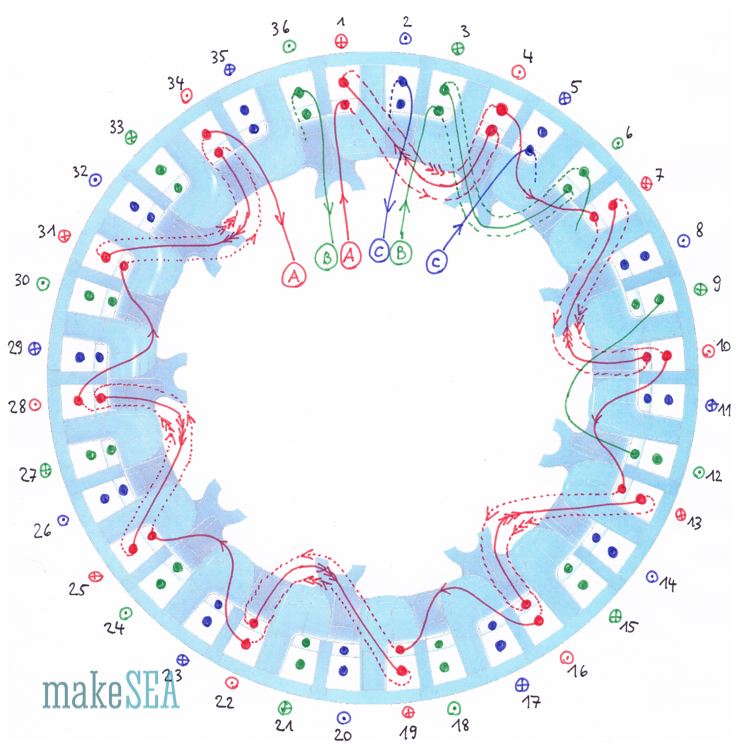
Each slot of the new stator has space for 4 wires. The illustration shows only 2 wires and only one phase for simplicity reasons. Continuous lines in the illustration are wires in the foreground, dotted lines are wires in the background. The big dots indicate wires in the slots, from front to back (or reverse). The “plus” in the circle indicates the direction from front to back, the “dot” in the circle indicates the opposite direction.
Before actually starting the winding of the magnetic PLA core, it’s recommended to exercise with some cheaper material. Maybe a test-print in ABS. Even though the winding pattern is not complicated, it’s not suited for beginners.1 Take your time - accurate and well fitting wires make it simpler to do the final turns.
1. I would recommend starting with thinner wire as it will be easier to get an accurate winding, and it will still yield power, just not as much as if you were to use thicker wire. Once you have tested the motor with the thinner wire then move onto the thicker wire. - D. Hartley
- Cut the copper wire into 3 pieces, each approximately 2.5 m long. Coil it on 3 small spools. These are the cables for phases A, B, and C.2
2. I would recommend starting with a full spool of wire and start the winding with phase A. Each set of winding requires approximately 2.5 m of wire, but it is much easier to wind the core using the spool as a tool to move the wire around. -D. Hartley
- Start winding phase A (red) with slot #1 on the front. Make sure the selected slot has a shape, where the cable is guided over the tooth-head between slot #1 and slot #2 (and not at the side). Position the wire into slot #1, and bend it on the back of the stator over the tooth-head towards slot #4. Wind the wire at the side of the tooth-head between slots #3 and #4. Position the wire into slot #4, and bend it then back toward slot #1. This was one turn. Repeat it 4 times (slots #1 and #4 will each have 4 wires). With the last turn, don’t bend the cable back towards slot #1 - the next slot would be #7,3 but we make a pause and continue with phase B (green). In order to fix the remaining cable, it can be temporarily positioned diametral into slot #22.
3. Continue with Phase A until you have finished the winding with the wire coming out of slot #34. -D. Hartley
- Continue winding phase B (green) starting with slot #3 (slot #2 will remain empty at the moment). Position it into slot #3 and slot #6. Do exactly the same as previously described for phase A, just with 2 slots offset. Use slot #24 as temporary fix.
- Continue analogous with phase C (blue) with slots #5 and #8.
- Slots #1, #3, #4, #5, #6, #8 are now all filled with 4 wires per slot. It’s time to continue with phase A (red), which had been temporarily fixed in slot #22. Reposition it to slot #7. This is the only bend, where the cable is not as well guided. Continue with the same winding patterns as initially, but now in slots #7 and #10. Again 4 turns. Then phase B, C. And so on …
- The very final turns of phase C (blue) are a bit more tricky. The pattern is the same, but the cables need to be led through the first coil of phase A.
- Done! Tea-time :-)
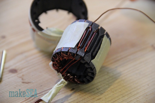
In the picture above one tooth-head is heavily bent upwards. It finally did break off. No real tragedy - it looks bad, and the unguided cables are more difficult to restrain, but the final functionality of the motor is not affected.
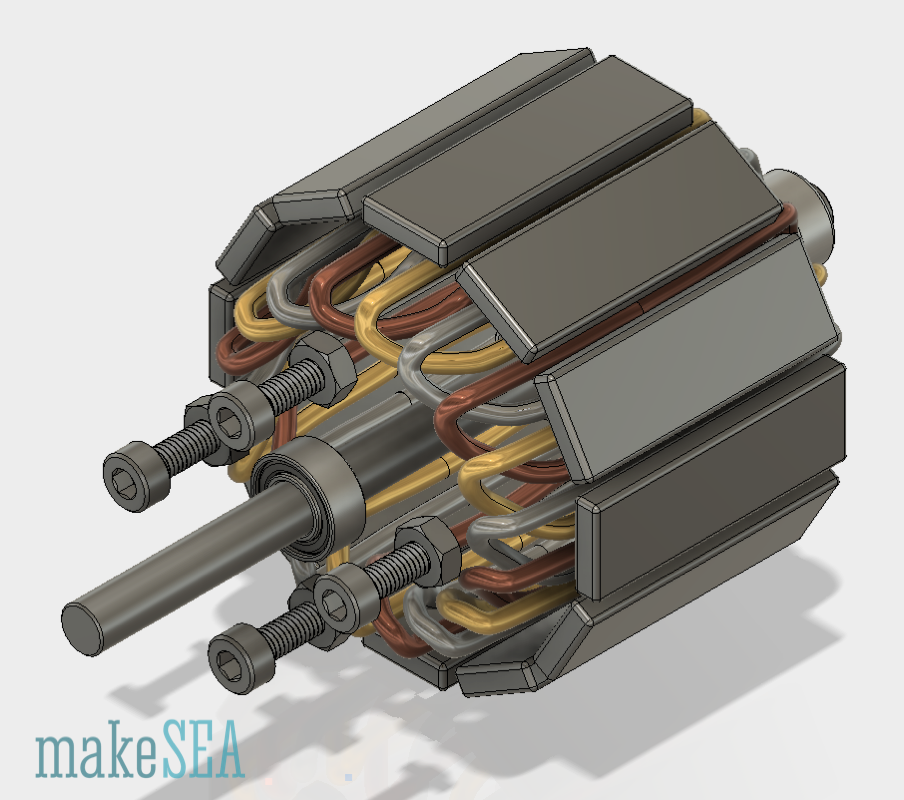
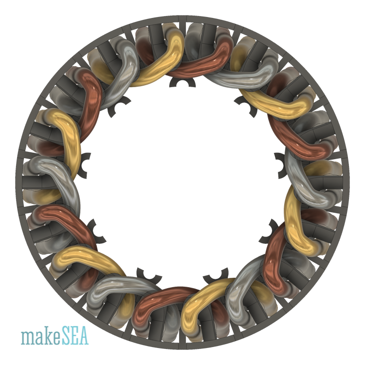
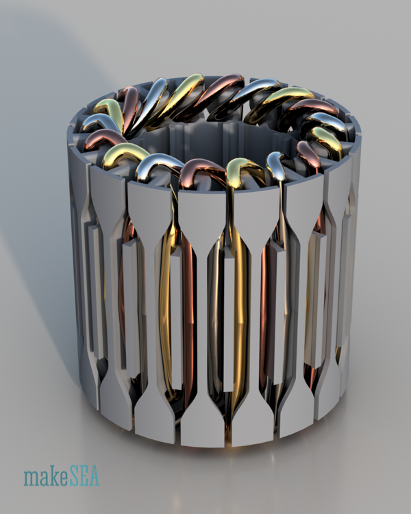
The 3 images below also illustrate the same the winding scheme. The three phases are colored in copper, gold, and silver. Instead of 4 individual wires, the illustration shows only a single fat wire per slot (easier visualization).

When all the winding is completed (after tea-time), the cables probably need to be pushed to their final position. Use a piece of wood or plastic, but no metal as it would damage the wire isolation. The rest of the assembly is the same as for makeSEA Model A001. It’s recommended to guide all the 6 ends out of the case, and connect it in a star-shape.4
4. Personally I used a credit card and toothpick and it worked great.
Tests and Measurements
The measurements are performed similar as for Model A001. Therefore less comments, and pure numbers.
| Wire Length per Phase (approx.) | 2200 | mm |
| Wire Diameter | 1.0 | mm |
| Resistivity Copper | 0.017 | Ohm*mm^2/m |
| Resistance per Phase (calculated) | 0.047 | Ohm |
Generator test (“drill-press method”) for measuring Kv:
| Rotation Speed | 1’060 | RPM |
| Amplitude Delta-Connection | 0.5 | V |
| Amplitude Star-Connection | 0.83 | V |
| Kv (Delta-Connection) | 1’344 | RPM / V |
Model A001 had Kv = 1’006 RPM / V with 3 turns per tooth. If the old stator was wound with only 2 turns per tooth (like the new stator), the motor had 1’509 RPM / V. Obviously the shorter teeth had their desired effect: less RPM, and more torque (and hopefully more efficiency).
OK! Mount the propeller, and connect the motor with the ESC from the RC-Car. Pushing carefully the throttle, the motor starts immediately and sounds “normal”. More throttle while continuously measuring the RPM - in order to be sure, the motor doesn’t exceed 10’000 RPM (which is hopefully a limit, where centrifugal forces are still small enough and the motor doesn’t break). At full throttle the current at the battery is 13 A and the motor spins approximately with 7’000 RPM. The propeller makes a powerful sound, generates a lot of airflow in the workshop (swirling all the dust). This is very promising. A whole series of measurements including the motor torque was taken. Again the same setup as for the previous Model A001.
| (measured) | (calculated) | (result) | |||||
| Battery Current [A] | Battery Voltage [V] | Motor Speed [RPM] | Motor Force [g] | Motor Torque [Nm] | Battery Power [W] | Motor Shaft Power [W] | Efficiency |
| 0.55 | 7.65 | 1'500 | 2.8 | 0.005 | 4.21 | 0.86 | 20.51% |
| 0.7 | 7.65 | 2'120 | 4 | 0.008 | 5.36 | 1.74 | 32.54% |
| 1.04 | 7.64 | 2'450 | 5.4 | 0.011 | 7.95 | 2.72 | 34.21% |
| 1.5 | 7.6 | 2'970 | 8.16 | 0.016 | 11.40 | 4.98 | 43.68% |
| 2.08 | 7.58 | 3'400 | 10.2 | 0.020 | 15.77 | 7.13 | 45.19% |
| 2.5 | 7.6 | 3'640 | 13 | 0.026 | 19.00 | 9.72 | 51.17% |
| 3.3 | 7.5 | 4'030 | 15 | 0.029 | 24.75 | 12.42 | 50.18% |
| 5 | 7.5 | 4'750 | 20.5 | 0.040 | 37.50 | 20.01 | 53.35% |
| 6 | 7.33 | 5'150 | 24.8 | 0.049 | 43.98 | 26.24 | 59.67% |
| 7.1 | 7.37 | 5'500 | 26.8 | 0.053 | 52.33 | 30.28 | 57.88% |
| 8.5 | 7.2 | 5'880 | 32.1 | 0.063 | 61.20 | 38.78 | 63.37% |
| 9.3 | 7.21 | 6'150 | 35.8 | 0.070 | 67.05 | 45.24 | 67.46% |
| 10.5 | 7.1 | 6'400 | 38.5 | 0.076 | 74.55 | 50.63 | 67.91% |
| 12.45 | 7 | 6'750 | 42 | 0.082 | 87.15 | 58.25 | 66.84% |
| 13 | 7.1 | 6'924 | 42 | 0.082 | 92.30 | 59.75 | 64.73% |
With 13 A Battery current and roughly 90 W power consumption, the overall system efficiency is at 65%. That’s more power and better efficiency compared with Model A001. The losses also includes losses from the ESC and all the cables! The efficiency of the motor itself is therefore bigger than 65%. The values seem plausible - running the motor for several minutes at full throttle (13 A) does not dramatically heat up the motor. Final temperature is 40°C (with 20°C room temperature).
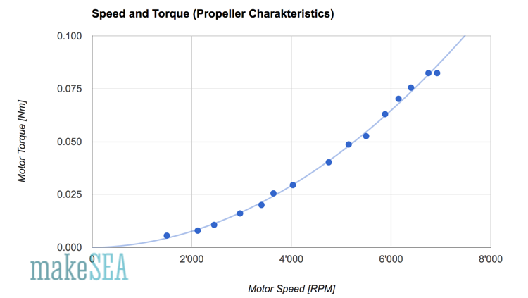
Comparing torque and speed: It underlines again the plausibility of the measured values.
Conclusions
Mission accomplished. Much more than 40°C is probably not healthy for the PLA stator. If the power was doubled, while the efficiency was unchanged, the temperature would probably go up to 60°C (PLA starts deforming). Further optimisation of efficiency would be required. However more than 80% is probably not realistic for a 3d-printed motor. Without changing the motor dimensions there are some options to increase the maximum power:
- Design with better cooling
- Maybe there is magnetic ABS or PETG? Or even leave away magnetic particles but use a material which can withstand higher temperatures up to 100°C?
- Use magnetic material for the rotor, use stronger magnets
- More copper, better filled slots (e.g. 3 turns with 0.85 mm wire)
- Even shorter teeth, cables not farther than 1 mm from the magnets
For a relevant increment of power the dimensions need to be increased. Larger diameter: e.g. 24 magnets, 72 slots, higher stator: e.g. 60 mm => Volume is 8 times larger. Maximum power is theoretically also 8 times higher, but cooling surface is only 4 times larger. Guessing power in the range from 500 W to 1 kW.
Datasheet
|
Diameter | 52.2 | mm |
| Continuous Power | 92 | W |
| Length | 54.0 | mm |
| Nominal Voltage | 7.1 | V |
| Overall Length (incl. Shaft) | 86.8 | mm |
| Nominal Current | 13 | A |
| Shaft Diameter | 5.0 | mm |
| Nominal Efficiency | 65 | % |
| Screw Hole Distance | 25.0 | mm |
| Nominal Speed | 6’920 | RPM |
| Screw Thread Size | M3 |
|
| Nominal Torque | 0.082 | Nm |
| Weight | 220 | g |
| Stator Height | 30 | mm |
| Resistance per Coil | 0.047 | Ohm |
| Stator Diameter (air gap) | 40 | mm |
| Poles | 12 |
|
|
|
|
|
| Slots | 36 |
|
|
|
|
|
| Turns | 2 |
|
|
|
|
|
| Wire Diameter | 1.00 | mm |
|
|
|
|
| Kv | 1’344 | RPM / V |
|
|
|
|
| No Load Current (I0) | 1.9 | A |
|
|
|
|
Related Videos:
RC Plane with 3-d printed motor and 3-d printed propeller
For our Spanish speaking members check out these videos by Manes Fernandez Cabanas, Associate Professor at the Universidad de Oviedo. He has documented his construction of the makeSEA brushless motor in a two part video on YouTube:
Part one is an overview of the project and the rotor.
Part two is about winding the stator.